

HOT Interconnects (HOTi) Summary- Part I. Building Large Scale Data Centers
Introduction:
The annual IEEE Hot Interconnects conference was held August 24-25, 2016 in Santa Clara, CA with several ½ day tutorials on August 25th. We review selected presentations in a series of conference summary articles. In this Part I. piece, we focus on design considerations for large scale Data Centers (DCs) that are operated by Cloud Service Providers (CSPs). If there is reader demand (via email requests to this author: [email protected]), we’ll generate a summary of the tutorial on Data Center Interconnection (DCI) methodologies.
Building Large Scale Data Centers: Cloud Network Design Best Practices, Ariel Hendel, Broadcom Limited
In his invited HOTi talk, Ariel examined the network design principles of large scale Data Centers designed and used by CSPs. He later followed up with additional information via email and phone conversations with this author. See Acknowledgment at the end of this article.
It’s important to note that this presentation was focused on intra-DC communications and NOT inter-DC or the cloud network access (e.g. type of WAN/Metro links) between cloud service provider DC and the customer premises WAN/metro access router.
Mr. Hendel’s key points:
- The challenges faced by designers of large DCs include: distributed applications, multi-tenancy, number and types of virtual machines (VMs), containers [1], large volumes of East-West (server-to-server) traffic, delivering low cost per endpoint, choice of centralized (e.g. SDN) or distributed (conventional hop by hop) Control plane for routing/path selection, power, cabling, cooling, satisfying large scale and incremental deployment.
Note 1. Containers are a solution to the problem of how to get software to run reliably when moved from one computing environment to another. This could be from a developer’s laptop to a test environment, from a staging environment into production and perhaps from a physical machine in a data center to a virtual machine in a private or public cloud.
- Most large-scale Data Centers have adopted a “scale- out” network model. This model is analogous to the “scale- out” server model for which the compute infrastructure is one size fits all. The network scale- out model is a good fit for the distributed software programming model used in contemporary cloud based compute servers.
- Distributed applications are the norm for public cloud deployments as application scale tends to exceed the capacity of any multi-processor based IT equipment in a large DC.
- The distributed applications are decomposed and deployed across multiple physical (or virtual) servers in the DC, which introduces network demands for intra-application communications.
- This evolving programming and deployment model is evolving to include parallel software clusters, micro-services, and machine learning clusters. All of these have ramifications on the corresponding network attributes.
- The cloud infrastructure further requires that multiple distributed applications coexist on the same server infrastructure and network infrastructure.
- The network design goal is a large-scale network that satisfies the workload requirements of cloud-distributed applications. This task is ideally accomplished by factoring in the knowledge of cloud operators regarding their own workloads.
- Post talk add-on: L3 (Network layer) routing has replaced L2 multi-port bridging in large scale DC networks, regardless of the type of Control plane (centralized/distributed) or routing protocol used at L3 (in many cases it’s BGP). Routing starts at the TOR and the subnets are no larger than a single rack. Therefore, there is no need for L2 Spanning Tree protocol as the sub net comprises only a single switch. There is absolute consensus on intra DC networks operating at L3, as opposed to HPC fabrics (like InfiniBand and Omnipath) which are L2 islands.
- Other DC design considerations include: North-South WAN Entry Points, Route Summarization, dealing with Traffic Hot Spots (and Congestion), Fault Tolerance, enabling Converged Networks, Instrumentation for monitoring, measuring and quantifying traffic, and Ethernet PMD sublayer choices for line rate (speed) and physical media type.
The concept of a DC POD [2] was introduced to illustrate a sub-network of IP/Ethernet switches and compute servers, which consist of: Leaf switches which are fully mesh connected via 100 GE to Top of Rack (TOR) switches, each of which connects to many compute servers in the same rack via 25GE copper.
Note 2. PODs provide a unit of incremental deployment of compute resources whose chronological order is independent of the applications they eventually host. PODs can also be the physical grouping of two adjacent tiers in the topology so that such tiers can be deployed with sets of switches that are in close physical proximity and with short average and maximum length cable runs. In the diagrams shown, the adjacent tiers are Leaf and TOR plus the compute servers below each TOR (in the same rack).
Author’s Note for clarification: Most storage area networks use Fibre Channel or InfiniBand (rather than Ethernet) for connectivity between storage server and storage switch fabric or between fabrics. Ariel showed Ethernet used for storage interconnects in his presentation for consistency. He later wrote this clarifying comment:
“The storage network part (of the DC) differs across cloud operators. Some have file servers connected to the IP/Ethernet network using NAS protocols, some have small SANs with a scale of a rack or a storage array behind the storage servers providing the block access, and others have just DAS on the servers and distributed file systems over the network. Block storage is done at a small scale (rack or storage array) using various technologies. It’s scalable over the DC network as NAS or distributed file systems.”
In the POD example given in Ariel’s talk, the physical characteristics were: 3.2T TOR, 6.4T Leaf, 100G uplinks, 32 racks, 1280 servers. Ariel indicated there were port speed increases ongoing to provide optimal “speeds and feeds” with no increase in the fiber/cabling plant. In particular:
- Compute servers are evolving from 10GE to 25GE interfaces (25GE uses the same number of 3m copper or fiber lanes as 10GE). That results in a 2.5x Higher Server Bandwidth Efficiency.
- Storage equipment (see note above about interface type for storage networks) are moving from 40GE to 50GE connectivity, where 50GE uses half the copper or fiber lanes than 40GE. That results in 2x Storage Node Connectivity, 25% More Bandwidth Per Node and 50% Fewer Cabling Elements versus 40GE.
- Switch Fabrics are upgrading from 40GE to 100GE backbone links which provides a 2.5X performance increase for every link in a 3-tier leaf-spine. There’s also Better Load Distribution and Lower Application Latency which results in an effective 15x increase in Fabric Bandwidth Capacity.
Ariel said there is broad consensus is the use of the “Leaf-Spine” topology model for large DC networks. In the figure below, Ariel shows how to interconnect the PODs in a leaf- spine configuration.
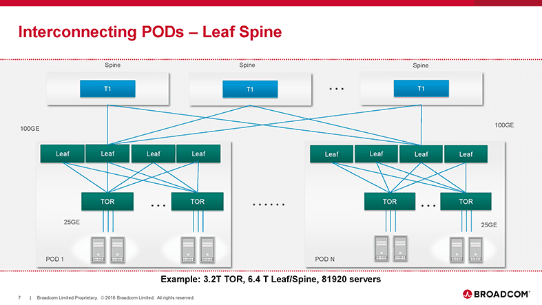
In a post conference phone conversation, Ariel added: “A very wide range of network sizes can be built with a single tier of spines connecting PODs. One such network might have as many as 80K endpoints that are 25GE or 50GE attached. More than half of the network cost, in this case, is associated with the optical transceivers.”
Ariel noted in his talk that the largest DCs have two spine tiers which are (or soon will be) interconnected using 100GE. The figure below illustrates how to scale the spines via either a single tier or dual spine topology.

“It is important to note that each two tier Spine shown in the above figure can be packaged inside a chassis or can be cabled out of discrete boxes within a rack. Some of the many ramifications of a choice between Spine chassis vs. Fixed boxes were covered during the talk.”
Ariel’s Acute Observations:
• Cost does not increase significantly with increase in endpoints.
• Endpoint Speed and ToR over subscription determine the cost/performance tradeoffs even in all
100G network.
• 100G network is “future proofed” for incremental or wholesale transition to 50G and 100G endpoints.
• 50G endpoint is not prohibitively more expensive than a 25G endpoint and is comparable at 2.5:1
over subscription of network traffic.
Our final figure is an illustration of the best way to connect to Metro and WAN – Edge PODs:

“When connecting all external traffic through the TOR or Leaf tier traffic is treated as any other regular endpoint traffic, it is dispersed, load balanced, and failed over completely by the internal Data Center network.”
Author’s Note: The type(s) of WAN-Metro links at the bottom of the figure are dependent on the arrangement between a cloud service and network provider. For example:
- AT&T’s Netbond let’s partner CSPs PoP be 1 or more endpoints of their customers IP VPN.
- Equinix Internet Exchange™ allows networks including ISPs, Content Providers and Enterprises to easily and effectively exchange Internet traffic.
- Amazon Virtual Private Cloud (VPC) lets the customer provision a logically isolated section of their Amazon Web Services (AWS) cloud where one can launch AWS resources in a virtual network that’s customer define.
Other Topics:
Mr. Hendel also mapped network best practices down to salient (Broadcom) switch and NIC silicon at the architecture and feature level. Congestion avoidance and management were discussed along with DC visibility and control. These are all very interesting, but that level of detail is beyond the scope of this HOTi conference summary.
Add-on: Important Attribute of Leaf-Spine Network Topology:
Such networks can provide “rearrangeable non-blocking” capacity by using traffic dispersion. In this case, traffic flows between sources and destinations attached to the leaf stage can follow multiple alternate paths. To the extent that such flows are placed optimally on these multiple paths, the network is non-blocking (it has sufficient capacity for all the flows).
Add-on: Other Network Topologies:
Actual network topologies for a given DC network are more involved than this initial concept. Their design depends on the following DC requirements:
1. Large (or ultra-large) Scale
2. Flat/low cost per endpoint attachment
3. Support for heavy E-W traffic patterns
4. Provide a logical as opposed to a physical network abstraction
5. Incrementally deployable (support a “pay as you grow” model)
Up Next:
We’ll review two invited talks on 1] DC network topology choices analyzed (it’s the diameter, stupid!) and 2] the impact of SDN and NFV on DC interconnects. An article summarizing the tutorial on Inter-DC networking (mostly software oriented) will depend on reader interest expressed via emails to this author.
Acknowledgment: The author sincerely thanks Ariel Hendel for his diligent review, critique and suggested changes/clarifications for this article.