

Advanced Antenna System
Tutorial on Advanced Antenna Systems (AAS) for 5G Networks
Editor’s Note:
Rec. ITU‑R M.2101 uses the term AAS to mean Advanced Antenna System(s), while 3GPP uses the term AAS to mean Active Antenna System (s).
Definition:
Advanced antenna systems (AAS) is the general term used to describe antenna systems utilizing techniques aiming at improving performance and spectral efficiency of radiocommunication transceivers taking advantage of antenna array theory and practice.
These techniques include adaptive beamforming, multiple input multiple output (MIMO), and space division multiple access (SDMA) among other ones. These multi-antenna techniques are generally applicable to any frequency band or radio application and can be implemented using passive or active antennas.
In higher frequency bands, such as those around the millimetric wave bands, active advanced antenna systems are the prevalent technology choice.
- Smart antennas
- Adaptive beamforming
- Phased arrays
- Spatial multiplexing and MIMO
- Space Division Multiple Access (SDMA)
- Active and passive antennas
- Antenna Array Theory
Basic concepts:
Multiple antennas can be arranged in space in specific configurations to form a highly directive pattern. These arrangements are referred to as “arrays.” In an array antenna, the fields from the individual elements add constructively in some directions and destructively (cancel) in others thus creating an overall array radiation pattern different from that of the individual elements.
The major advantage of antenna arrays over a single antenna element is their electronic scanning capability; that is, the major lobe can be steered toward any direction by changing the phase of the excitation current at each array element (phased array antennas). Furthermore, by also controlling the magnitude of the excitation current, a large variety of radiation patterns and sidelobe level characteristics can be produced. Adaptive antennas (also called “smart antennas” in mobile communication applications) go a step further than phased arrays and can direct their main lobe (with increased gain) in a desired direction (e.g., a mobile user in a cellular communication system) and nulls in the directions of interference or jammers.
AAS enables state-of-the-art beamforming and MIMO techniques that are powerful tools for improving end-user experience, capacity and coverage. As a result, AAS significantly enhances network performance in both uplink and downlink. Finding the most suitable AAS variants to achieve performance gains and cost efficiency in a specific network deployment requires an understanding of the characteristics of both AAS and of multi-antenna features.
Multi-antenna techniques
Multi-antenna techniques, here referred to as AAS features, include beamforming and MIMO. Such features are already used with conventional systems in today’s LTE networks. Applying AAS features to an AAS radio results in significant performance gains because of the higher degrees of freedom provided by the larger number of radio chains, also referred to as Massive MIMO.
Beamforming
When transmitting, beamforming is the ability to direct radio energy through the radio channel toward a specific receiver, as shown in the top left quadrant of Figure 1. By adjusting the phase and amplitude of the transmitted signals, constructive addition of the corresponding signals at the UE receiver can be achieved, which increases the received signal strength and thus the end-user throughput. Similarly, when receiving, beamforming is the ability to collect the signal energy from a specific transmitter. The beams formed by an AAS are constantly adapted to the surroundings to give high performance in both UL and DL.
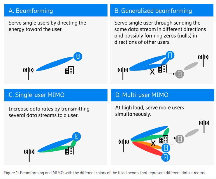
Although often very effective, transmitting energy in only one direction does not always provide an optimum solution. In multi-path scenarios, where the radio channel comprises multiple propagation paths from transmitter to receiver through diffraction around corners and reflections against buildings or other objects, it is beneficial to send the same data stream in several different paths (direction and/or polarization) with phases and amplitudes controlled in a way that they add constructively at the receiver. This is referred to as generalized beamforming, as shown in the upper right quadrant of Figure 1. As part of generalized beamforming, it is also possible to reduce interference to other UEs, which is known as null forming. This is achieved by controlling the transmitted signals in a way that they cancel each other out at the interfered UEs.
MIMO (Multiple Input, Multiple Output) techniques:
Spatial multiplexing, here referred to as MIMO, is the ability to transmit multiple data streams, using the same time and frequency resource, where each data stream can be beamformed. The purpose of MIMO is to increase throughput. MIMO builds on the basic principle that when the received signal quality is high, it is better to receive multiple streams of data with reduced power per stream, than one stream with full power. The potential is large when the received signal quality is high and the streams do not interfere with each other. The potential diminishes when the mutual interference between streams increases. MIMO works in both UL and DL, but for simplicity the description below will be based on the DL.
Single-user MIMO (SU-MIMO) is the ability to transmit one or multiple data streams, called layers, from one transmitting array to a single user. SU-MIMO can thereby increase the throughput for that user and increase the capacity of the network. The number of layers that can be supported, called the rank, depends on the radio channel. To distinguish between DL layers, a UE needs to have at least as many receiver antennas as there are layers.
SU-MIMO can be achieved by sending different layers on different polarizations in the same direction. SU-MIMO can also be achieved in a multi path environment, where there are many radio propagation paths of similar strength between the AAS and the UE, by sending different layers on different propagation paths, as shown in the bottom left quadrant of Figure 1.
In multi-user MIMO (MU-MIMO), which is shown in the bottom right quadrant of Figure 1. above, the AAS simultaneously sends different layers in separate beams to different users using the same time and frequency resource, thereby increasing the network capacity. In order to use MU-MIMO, the system needs to find two or more users that need to transmit or receive data at the very same time. Also, for efficient MU-MIMO, the interference between the users should be kept low. This can be achieved by using generalized beamforming with null forming such that when a layer is sent to one user, nulls are formed in the directions of the other simultaneous users.
The achievable capacity gains from MU-MIMO depend on receiving each layer with good signal-to-interference-and-noise-ratio (SINR). As with SU-MIMO, the total DL power is shared between the different layers, and therefore the power (and thus SINR) for each user is reduced as the number of simultaneous MU-MIMO users increases. As the number of users grows, the SINR will further deteriorate due to mutual interference between the users. The wireless network capacity (the number of devices that can use a wireless network at the same time and the bandwidth consumed) typically improves as the number of MIMO layers increases, to a point at which power sharing and interference between users result in diminishing gains, and eventually losses.
It should be noted that the practical benefits of many layers in MU-MIMO are limited by the fact that in today’s real networks, even with a high number of simultaneous connected users, there tends not to be many users who want to receive data simultaneously. This is due to the bursty (chatty) nature of data transmission to most users. Since the AAS and the transport network must be dimensioned for the maximum number of layers, the MNO needs to consider how many layers are required in their networks. In typical MBB deployments with the current 64T64R AAS variants, the vast majority of the DL and UL capacity gains can be achieved with up to 8 layers.
References:
https://www.ericsson.com/en/reports-and-papers/white-papers/advanced-antenna-systems-for-5g-networks