

Using a distributed synchronized fabric for parallel computing workloads- Part II
by Run Almog Head of Product Strategy, Drivenets (edited by Alan J Weissberger)
Introduction:
In the previous part I article, we covered the different attributes of AI/HPC workloads and the impact this has on requirements from the network that serves these applications. This concluding part II article will focus on an open standard solution that addresses these needs and enables these mega sized applications to run larger workloads without compromising on network attributes. Various solutions are described and contrasted along with a perspective from silicon vendors.
Networking for HPC/AI:
A networking solution serving HPC/AI workloads will need to carry certain attributes. Starting with scale of the network which can reach thousands of high speed endpoints and having all these endpoints run the same application in a synchronized manner. This requires the network to run like a scheduled fabric that offers full bandwidth between any group of endpoints at any given time.
Distributed Disaggregated Chassis (DDC):
DDC is an architecture that was originally defined by AT&T and contributed to the Open Compute Project (OCP) as an open architecture in September 2019. DDC defines the components and internal connectivity of a network element that is purposed to serve as a carrier grade network router. As opposed to the monolithic chassis-based router, the DDC defines every component of the router as a standalone device.
- The line card of the chassis is defined as a distributed chassis packet-forwarder (DCP)
- The fabric card of the chassis is defined as a distributed chassis fabric (DCF)
- The routing stack of the chassis is defined as a distributed chassis controller (DCC)
- The management card of the chassis is defined as a distributed chassis manager (DCM)
- All devices are physically connected to the DCM via standard 10GbE interfaces to establish a control and a management plane.
- All DCP are connected to all DCF via 400G fabric interfaces in a Clos-3 topology to establish a scheduled and non-blocking data plane between all network ports in the DDC.
- DCP hosts both fabric ports for connecting to DCF and network ports for connecting to other network devices using standard Ethernet/IP protocols while DCF does not host any network ports.
- The DCC is in fact a server and is used to run the main base operating system (BaseOS) that defines the functionality of the DDC
Advantages of the DDC are the following:
- It’s capacity since there is no metal chassis enclosure that needs to hold all these components into a single machine. This allows building a wider Clos-3 topology that expands beyond the boundaries of a single rack making it possible for thousands of interfaces to coexist on the same network element (router).
- It is an open standard definition which makes it possible for multiple vendors to implement the components and as a result, making it easier for the operator (Telco) to establish a multi-source procurement methodology and stay in control of price and supply chain within his network as it evolves.
- It is a distributed array of components that each has an ability to exist as a standalone as well as act as part of the DDC. This gives a very high level of resiliency to services running over a DDC based router vs. services running over a chassis-based router.
AT&T announced they use DDC clusters to run their core MPLS in a DriveNets based implementation and as standalone edge and peering IP networks while other operators worldwide are also using DDC for such functionality.
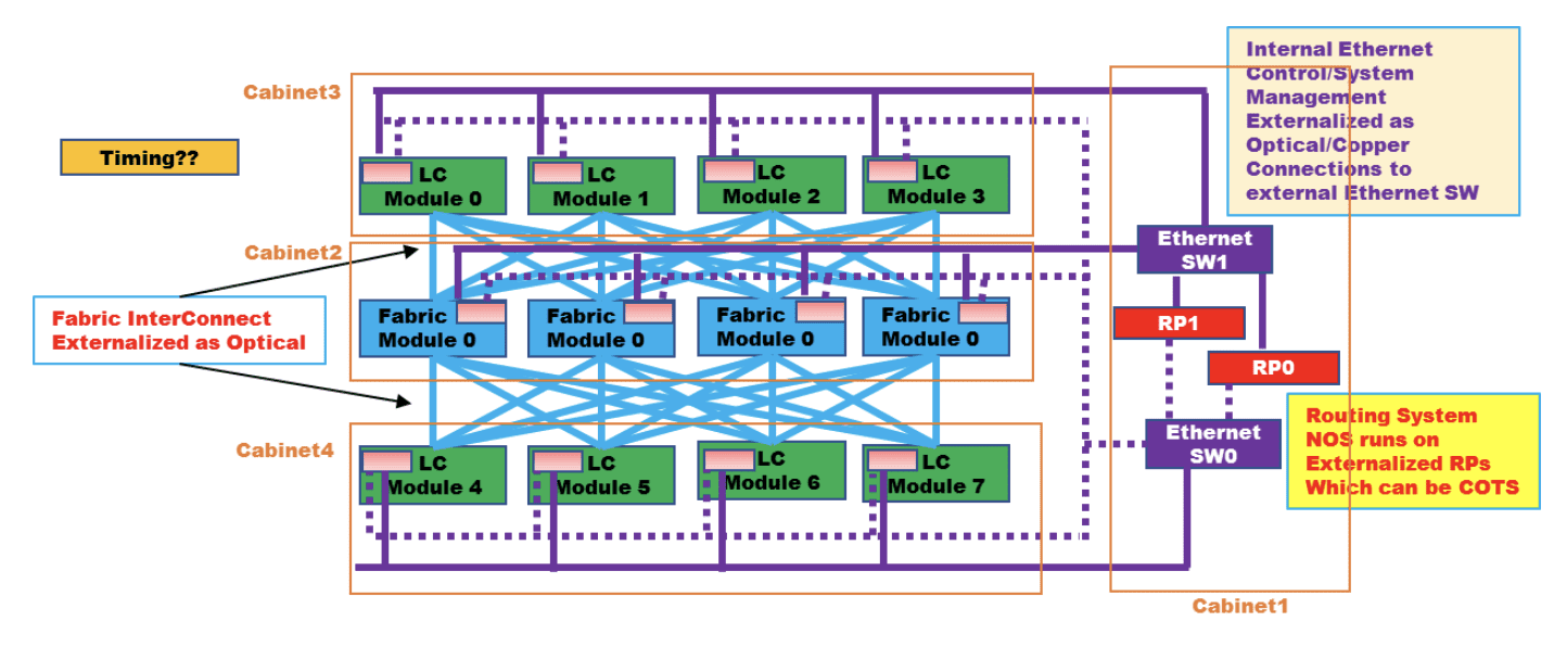
Figure 1: High level connectivity structure of a DDC
……………………………………………………………………………………………………………………………………………………..
LC is defined as DCP above, Fabric module is defined as DCF above, RP is defined as DCC above, Ethernet SW is defined as DCM above
Source: OCP DDC specification
DDC is implementing a concept of disaggregation. The decoupling of the control plane from data plane enables the sourcing of the software and hardware from different vendors and assembling them back into a unified network element when deployed. This concept is rather new but still has had a lot of successful deployments prior to it being used as part of DDC.
Disaggregation in Data Centers:
The implementation of a detached data plane from the control plane had major adoption in data center networks in recent years. Sourcing the software (control plane) from one vendor while the hardware (data plane) is sourced from a different vendor mandate that the interfaces between the software and hardware be very precise and well defined. This has brought up a few components which were developed by certain vendors and contributed to the community to allow for the concept of disaggregation to go beyond the boundaries of implementation in specific customers networks.
Such components include open network install environment (ONIE) which enables mounting of the software image onto a platform (typically a single chip 1RU/2RU device) as well as the switch abstraction interface (SAI) which enable the software to directly access the application specific integrated circuit (ASIC) and operate directly onto the data plane at line rate speeds.
Two examples of implementing disaggregation networking in data centers are:
- Microsoft which developed their network operating system (NOS) software Sonic as one that runs on SAI and later contributed its source code to the networking community via OCP and he Linux foundation.
- Meta has defined devices called “wedge” who are purpose built to assume various NOS versions via standard interfaces.
These two examples of hyperscale companies are indicative to the required engineering effort to develop such interfaces and functions. The fact that such components have been made open is what enabled other smaller consumers to enjoy the benefits of disaggregation without the need to cater for large engineering groups.
The data center networking world today has a healthy ecosystem with hardware (ASIC and system) vendors as well as software (NOS and tools) which make a valid and widely used alternative to the traditional monolithic model of vertically integrated systems.
Reasons for deploying a disaggregated networking solution are a combination of two. First, is a clear financial advantage of buying white box equipment vs. the branded devices which carry a premium price. Second, is the flexibility which such solution enables, and this enables the customer to get better control over his network and how it’s run, as well as enable the network administrators a lot of room to innovate and adapt their network to their unique and changing needs.
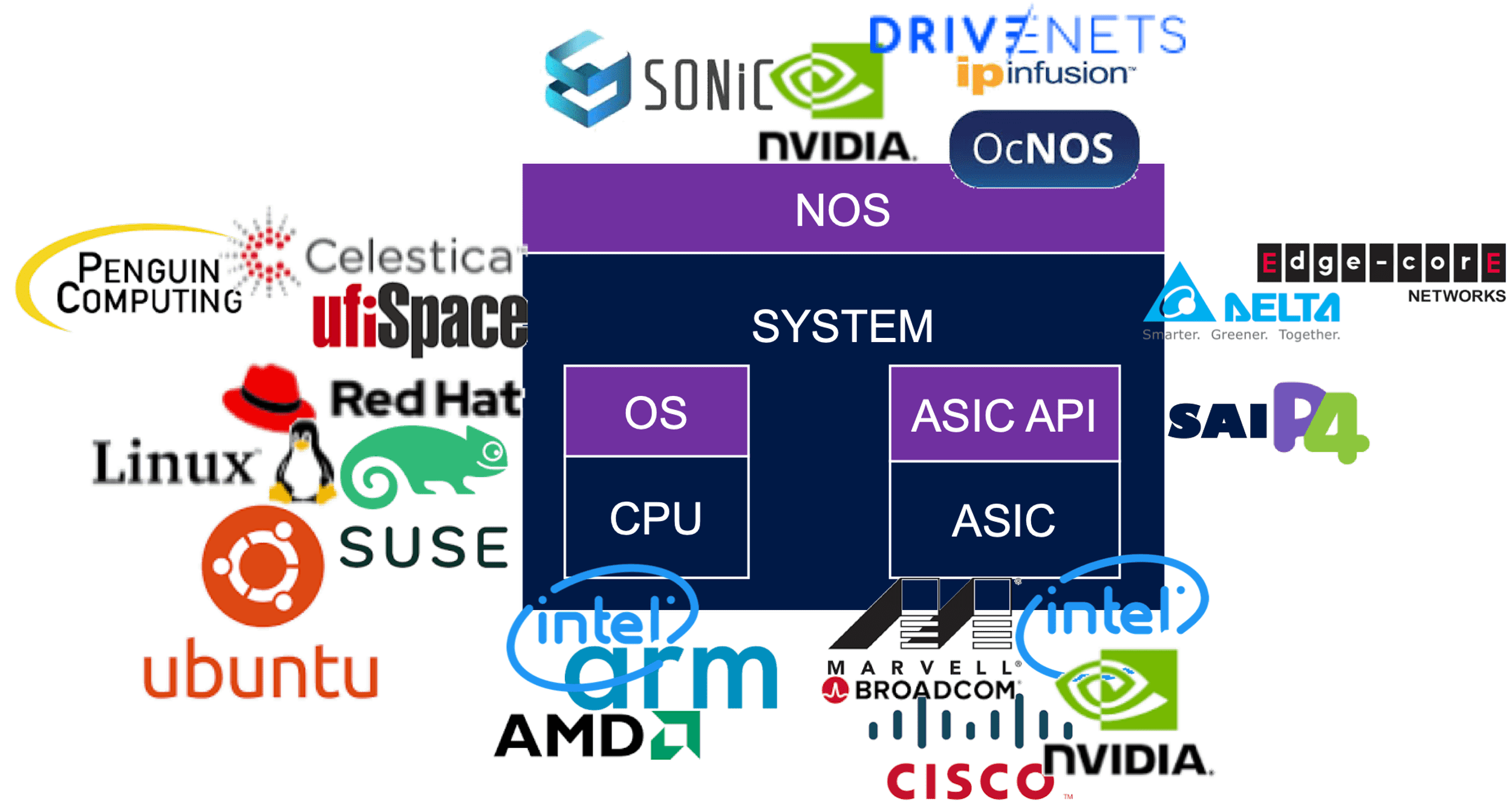
The image below reflects a partial list of the potential vendors supplying components within the OCP networking community. The full OCP Membership directory is available at the OCP website.
Between DC and Telco Networking:
Data center networks are built to serve connectivity towards multiple servers which contain data or answer user queries. The size of data as well as number of queries towards it is a constantly growing function as humanity grows its consumption model of communication services. Traffic in and out of these servers is divided to north/south that indicates traffic coming in and goes out of the data center, and east/west that indicates traffic that runs inside the data center between different servers.
As a general pattern, the north/south traffic represent most of the traffic flows within the network while the east/west traffic represent the most bandwidth being consumed. This is not an accurate description of data center traffic, but it is accurate enough to explain the way data center networks are built and operated.
A data center switch connects to servers with a high-capacity link. This tier#1 switch is commonly known as a top of rack (ToR) switch and is a high capacity, non-blocking, low latency switch with some minimal routing capabilities.
- The ToR is then connected to a Tier#2 switch that enables it to connect to other ToR in the data center.
- The Tier#2 switches are connected to Tier#3 to further grow the connectivity.
- Traffic volumes are mainly east/west and best kept within the same Tier of the network to avoid scaling the routing tables.
- In theory, a Tier#4/5/6 of this network can exist, but this is not common.
- The higher Tier of the data center network is also connected to routers which interface the data center to the outside world (primarily the Internet) and these routers are a different design of a router than the tiers of switching devices mentioned earlier.
- These externally facing routers are commonly connected in a dual homed logic to create a level of redundancy for traffic to come in and out of the datacenter. Further functions on the ingress and egress of traffic towards data centers are also firewalled, load-balanced, address translated, etc. which are functions that are sometimes carried by the router and can also be carried by dedicated appliances.
As data centers density grew to allow better service level to consumers, the amount of traffic running between data center instances also grew and data center interconnect (DCI) traffic became predominant. A DCI router on the ingress/egress point of a data center instance is now a common practice and these devices typically connect over larger distance of fiber connectivity (tens to hundreds of Km) either towards other DCI routers or to Telco routers that is the infrastructure of the world wide web (AKA the Internet).
While data center network devices shine is their high capacity and low latency and are built from the ASIC level via the NOS they run to optimize on these attributes, they lack in their capacity for routing scale and distance between their neighboring routers. Telco routers however are built to host enough routes that “host” the Internet (a ballpark figure used in the industry is 1M routes according to CIDR) and a different structure of buffer (both size and allocation) to enable long haul connectivity. A telco router has a superset of capabilities vs. a data center switch and is priced differently due to the hardware it uses as well as the higher software complexity it requires which acts as a filter that narrows down the number of vendors that provide such solutions.
Attributes of an AI Cluster:
As described in a previous article HPC/AI workloads demand certain attributes from the network. Size, latency, lossless, high bandwidth and scale are all mandatory requirements and some solutions that are available are described in the next paragraphs.
Chassis Based Solutions:
This solution derives from Telco networking.
Chassis based routers are built as a black box with all its internal connectivity concealed from the user. It is often the case that the architecture used to implement the chassis is using line cards and fabric cards in a Clos-3 topology as described earlier to depict the structure of the DDC. As a result of this, the chassis behavior is predictable and reliable. It is in fact a lossless fabric wrapped in sheet metal with only its network interfaces facing the user. The caveat of a chassis in this case is its size. While a well-orchestrated fabric is a great fit for the network needs of AI workloads, it’s limited capacity of few hundred ports to connect to servers make this solution only fitting very small deployments.
In case chassis is used at a scale larger than the sum number of ports per single chassis, a Clos (this is in fact a non-balanced Clos-8 topology) of chassis is required and this breaks the fabric behavior of this model.
Standalone Ethernet Solutions:
This solution derives from data center networking.
As described previously in this paper, data center solutions are fast and can carry high bandwidth of traffic. They are however based on standalone single chip devices connected in a multi-tiered topology, typically a Clos-5 or Clos-7. as long as traffic is only running within the same device in this topology, behavior of traffic flows will be close to uniform. With the average number of interfaces per such device limited to the number of servers physically located in one rack, this single ToR device cannot satisfy the requirements of a large infrastructure. Expanding the network to higher tiers of the network also means that traffic patterns begin to alter, and application run-to-completion time is impacted. Furthermore, add-on mechanisms are mounted onto the network to turn the lossy network into a lossless one. Another attribute of the traffic pattern of AI workloads is the uniformity of the traffic flows from the perspective of the packet header. This means that the different packets of the same flow, will be identified by the data plane as the same traffic and be carried in the exact same path regardless of the network’s congestion situation, leaving parts of the Clos topology poorly utilized while other parts can be overloaded to a level of traffic loss.
Proprietary Locked Solutions:
Additional solutions in this field are implemented as a dedicated interconnect for a specific array of servers. This is more common in the scientific domain of heavy compute workloads, such as research labs, national institutes, and universities. As proprietary solutions, they force
the customer into one interconnect provider that serves the entire server array starting from the server itself and ending on all other servers in the array.
The nature of this industry is such where a one-time budget is allocated to build a “super-computer” which means that the resulting compute array is not expected to further grow but only be replaced or surmounted by a newer model. This makes the vendor-lock of choosing a proprietary interconnect solution more tolerable.
On the plus side of such solutions, they perform very well, and you can find examples on the top of the world’s strongest supercomputers list which use solutions from HPE (Slingshot), Intel (Omni-Path), Nvidia (InfiniBand) and more.
Perspective from Silicon Vendors:
DSF like solutions have been presented in the last OCP global summit back in October-2022 as part of the networking project discussions. Both Broadcom and Cisco (separately) have made claims of superior silicon implementation with improved power consumption or a superior implementation of a Virtual Output Queueing (VOQ) mechanism.
Conclusions:
There are differences between AI and HPC workloads and the required network for each.
While the HPC market finds proprietary implementations of interconnect solutions acceptable for building secluded supercomputers for specific uses, the AI market requires solutions that allow more flexibility in their deployment and vendor selection. This boils down to Ethernet based solutions of various types.
Chassis and standalone Ethernet based solutions provide reasonable solutions up to the scale of a single machine but fail to efficiently scale beyond a single interconnect machine and keep the required performance to satisfy the running workloads.
A distributed fabric solution presents a standard solution that matches the forecasted industry need both in terms of scale and in terms of performance. Different silicon implementations that can construct a DSF are available. They differ slightly but all show substantial benefits vs. chassis or standard ethernet solutions.
This paper does not cover the different silicon types implementing the DSF architecture but only the alignment of DSF attributes to the requirements from interconnect solutions built to run AI workloads and the advantages of DSF vs. other solutions which are predominant in this space.
–>Please post a comment in the box below this article if you have any questions or requests for clarification for what we’ve presented here and in part I.
References:
Using a distributed synchronized fabric for parallel computing workloads- Part I