

IMT 2020 RIT
India’s TSDSI candidate IMT 2020 RIT with Low Mobility Large Cell (LMLC) for rural coverage of 5G services
India’s telecom standards organization TSDSI has submitted its candidate IMT-2020 Radio Interface Technology (RIT) to the IMT-2020 evaluation at the ITU-R WP 5D meeting #32 being held in Buzios, Brazil from 9 July 2019 to 17 July 2019. TSDSI’s IMT 2020 submission is one of five candidate RIT proposals- see NOTE at bottom of this article for more information.
TSDSI’s RIT is described in document ITU-R WP5D-AR Contribution 770. This RIT has been developed to address the rural requirements by enabling the implementation of Low Mobility Large Cell (LMLC), particularly with emphasis on low-cost rural coverage of 5G wireless network services. TSDSI believes that this RIT will also help to meet the rural requirements of other developing countries. This author agrees!
TSDSI proposal on Low Mobility Large Cell (LMLC) configuration has been included as a mandatory test configuration under the Rural eMBB (enhanced Mobile BroadBand) test environment in IMT 2020 Technical Performance Requirements (TPR) in ITU-R with an enhanced Inter Sire Distance (ISD) of 6 km. Incorporation of LMLC in IMT2020 will help address the requirements of typical Indian rural settings and will be a key enabler for bridging the rural-urban divide with 5G rollouts.
–>The Indian administration (ITU member country) extends its support to the RIT of TSDSI and solicits the support of ITU Member States to support this proposal.
Indian wireless network operators, including Reliance Jio Infocomm Ltd, have expressed interest in LMLC.
About TSDSI:
*TSDSI is a Standards development organization similar to ETSI, SRIB, ATIS, CCSA, TTA, TTC, etc.
*TSDSI is an Organisational Partner of 3GPP and oneM2M, an Associate member of ITU-R and ITU-T and a member of GSC.
*TSDSI delegations have been actively participating and contributing in Standards development Working Groups in all these forums.
*TSDSI has formal affiliations (MoUs/Agreements) with – ETSI, 5GIA, ATSC, BIF, CCICI, GCF, IEEE-SA, TIA, TAICs, TTA, WWRF, ARIB, ATIS, CCSA, TTC
*TSDSI conducts several joint activities – projects, workshops, conferences etc. with its affiliates
*TSDSI’s operating procedures have been derived based on best practices being followed by similar Global SDOs.
*TSDSI Rules & Regulations, Working Procedures and IPR Policy are all transparent and available on our website – http://www.tsdsi.in. A brief perusal will show the similarity with the processes and policies followed by other SDOs.
*TSDSI strictly follows the Rules and Procedures. It provides an open, transparent and collaborative platform for its members to participate and contribute in the development of Standards with a special focus on India Specific Requirements and Indian Innovations. The governance model is also very inclusive, open and transparent with fresh elections being conducted for all positions every 2 years.
Submitted by: Chair TSDSI , Vice Chair TSDSI and DG TSDSI
http://www.tsdsi.in
………………………………………………………………………………………………………………………………………….
Kiran Kumar Kuchi, a professor at IIT Hyderabad is building a 5G testbed there. The system will exceed IMT 2020 5G performance requirements including Low Mobility Large Cell.
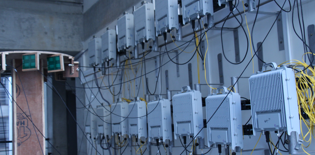
IIT Hyderabad 5G Testbed. Photo courtesy of IIT Hyderabad.
……………………………………………………………………………………………………………………………………………………………………………………………………………
TSDSI’s baseline RIT (initial description template) is documented in ITU-R WP 5D Document 5D/980: Revision 2 to Document IMT-2020/7-E, submitted on 14 February 2019. Several updates to TSDSI RIT included the updated characteristics template, initial link budget template, etc. They are in Document 5D/1138: Attachment Part 1: 5D/1138!P1; Attachment Part 2: 5D/1138!P2; Attachment Part 3: 5D/1138!P3; Attachment Part 4: 5D/1138!P4)
Here are a few key excerpts from the TSDSI baseline RIT:
Describe details of the radio interface architecture and protocol stack such as: – Logical channels – Control channels – Traffic channels Transport channels and/or physical channels.
RAN/Radio Architectures: This RIT contains NR standalone architecture. The following paragraphs provide a high-level summary of radio interface protocols and channels.
Radio Protocols: The protocol stack for the user plane includes the following: SDAP, PDCP, RLC, MAC, and PHY sublayers (terminated in UE and gNB). On the Control plane, the following protocols are defined: – RRC, PDCP, RLC, MAC and PHY sublayers (terminated in UE and gNB); – NAS protocol (terminated in UE and AMF) For details on protocol services and functions, please refer to 3GPP specifications (e.g. [38.300]).
Radio Channels (Physical, Transport and Logical Channels):
- The physical layer offers service to the MAC sublayer transport channels. The MAC sublayer offers service to the RLC sublayer logical channels.
- The RLC sublayer offers service to the PDCP sublayer RLC channels.
- The PDCP sublayer offers service to the SDAP and RRC sublayer radio bearers: data radio bearers (DRB) for user plane data and signalling radio bearers (SRB) for control plane data.
- The SDAP sublayer offers 5GC QoS flows and DRBs mapping function.
The physical channels defined in the downlink are: – the Physical Downlink Shared Channel (PDSCH), – the Physical Downlink Control Channel (PDCCH), – the Physical Broadcast Channel (PBCH).
The physical channels defined in the uplink are: – the Physical Random Access Channel (PRACH), – the Physical Uplink Shared Channel (PUSCH), – and the Physical Uplink Control Channel (PUCCH). In addition to the physical channels above, PHY layer signals are defined, which can be reference signals, primary and secondary synchronization signals.
The following transport channels, and their mapping to PHY channels, are defined:
Uplink: – Uplink Shared Channel (UL-SCH), mapped to PUSCH – Random Access Channel (RACH), mapped to PRACH
Downlink: – Downlink Shared Channel (DL-SCH), mapped to PDSCH – Broadcast channel (BCH), mapped to PBCH – Paging channel (PCH), mapped to (TBD)
Logical channels are classified into two groups: Control Channels and Traffic Channels.
Control channels: – Broadcast Control Channel (BCCH): a downlink channel for broadcasting system control information. – Paging Control Channel (PCCH): a downlink channel that transfers paging information and system information change notifications. – Common Control Channel (CCCH): channel for transmitting control information between UEs and network. – Dedicated Control Channel (DCCH): a point-to-point bi-directional channel that transmits dedicated control information between a UE and the network.
Traffic channels: Dedicated Traffic Channel (DTCH), which can exist in both UL and DL. In Downlink, the following connections between logical channels and transport channels exist: – BCCH can be mapped to BCH, or DL-SCH; – PCCH can be mapped to PCH; – CCCH, DCCH, DTCH can be mapped to DL-SCH;
In Uplink, the following connections between logical channels and transport channels exist: – CCCH, DCCH, DTCH can be mapped to UL-SCH.
Enhancements:
1. Method to improve broadcast and paging control channel efficiency over access elements.
2. Reduce the impact of congestion in the data path and control path to improve overall efficiency in the network.
3. Other aspects
– NR QoS architecture The QoS architecture in NG-RAN (connected to 5GC), can be summarized as follows: For each UE, 5GC establishes one or more PDU Sessions. For each UE, the NG-RAN establishes one or more Data Radio Bearers (DRB) per PDU Session. The NG-RAN maps packets belonging to different PDU sessions to different DRBs. Hence, the NG-RAN establishes at least one default DRB for each PDU Session. NAS level packet filters in the UE and in the 5GC associate UL and DL packets with QoS Flows. AS-level mapping rules in the UE and in the NG-RAN associate UL and DL QoS Flows with DRBs
– Carrier Aggregation (CA) In case of CA, the multi-carrier nature of the physical layer is only exposed to the MAC layer for which one HARQ entity is required per serving cell.
– Dual Connectivity (DC) In DC, the radio protocol architecture that a radio bearer uses depends on how the radio bearer is setup.
…………………………………………………………………………………………………………..
Four bearer types (information carrying channels) exist: MCG bearer, MCG split bearer, SCG bearer and SCG split bearer.
The following terminology/definitions apply:
– Master gNB: in dual connectivity, the gNB which terminates at least NG-C.
– Secondary gNB: in dual connectivity, the gNB that is providing additional radio resources for the UE but is not the Master node.
– Master Cell Group (MCG): in dual connectivity, a group of serving cells associated with the MgNB
– Secondary Cell Group (SCG): in dual connectivity, a group of serving cells associated with the SgNB
– MCG bearer: in dual connectivity, a bearer whose radio protocols are only located in the MCG.
– MCG split bearer: in dual connectivity, a bearer whose radio protocols are split at the MgNB and belong to both MCG and SCG.
– SCG bearer: in dual connectivity, a bearer whose radio protocols are only located in the SCG.
– SCG split bearer: in dual connectivity, a bearer whose radio protocols are split at the SgNB and belong to both SCG and MCG.
In case of DC, the UE is configured with two MAC entities: one MAC entity for the MCG and one MAC entity for the SCG. For a split bearer, UE is configured over which link (or both) the UE transmits UL PDCP PDUs. On the link which is not responsible for UL PDCP PDUs transmission, the RLC layer only transmits corresponding ARQ feedback for the downlink data.
What is the bit rate required for transmitting feedback information? The information will be provided in later update.
……………………………………………………………………………………………………………………
LMLC Detailed Description – Characteristics template for TSDSI RIT:
The description template provides the characteristics description of the TSDSI RIT.
For this characteristic template, it has chosen to address the characteristics that are viewed to be very crucial to assist in evaluation activities for independent evaluation groups, as well as to facilitate the understanding of the RIT.
Channel access: Describe in detail how RIT/SRIT accomplishes initial channel access, (e.g. contention or non-contention based).
Initial channel access is typically accomplished via the “random access procedure” (assuming no dedicated/scheduled resources are allocated). The random access procedure can be contention based (e.g. at initial connection from idle mode) or non-contention based (e.g. during Handover to a new cell). Random access resources and parameters are configured by the network and signaled to the UE (via broadcast or dedicated signaling). Contention based random access procedure encompasses the transmission of a random access preamble by the UE (subject to possible contention with other UEs), followed by a random access response (RAR) in DL (including allocating specific radio resources for the uplink transmission). Afterwards, the UE transmits the initial UL message (e.g. RRC connection Request) using the allocated resources, and wait for a contention resolution message in DL (to confirming access to that UE). The UE could perform multiple attempts until it is successful in accessing the channel or until a timer (supervising the procedure) elapses. Non-contention based random access procedure foresees the assignment of a dedicated random access resource/preamble to a UE (e.g. part of an HO command). This avoids the contention resolution phase, i.e. only the random access preamble and random access response messages are needed to get channel access.
From a PHY perspective, a random access preamble is transmitted (UL) in a PRACH, random access response (DL) in a PDSCH, UL transmission in a PUSCH, and contention resolution message (DL) in a PDSCH.
……………………………………………………………………………………………………………………
| Radio interface functional aspects: | ||||||||||||||||||
| Multiple access schemes
Which access scheme(s) does the proposal use? Describe in detail the multiple access schemes employed with their main parameters. – Downlink and Uplink: The multiple access is a combination of ● OFDMA: Synchronous/scheduling-based; the transmission to/from different UEs uses mutually orthogonal frequency assignments. Granularity in frequency assignment: One resource block consisting of 12 subcarriers. Multiple sub-carrier spacings are supported including 15kHz, 30kHz, 60kHz and 120kHz for data (see Item 5.2.3.2.7 and reference therein). 1. CP-OFDM is applied for downlink. DFT-spread OFDM and CP-OFDM are available for uplink. 2. Spectral confinement technique(s) (e.g. filtering, windowing, etc.) for a waveform at the transmitter is transparent to the receiver. When such confinement techniques are used, the spectral utilization ratio can be enhanced. ● TDMA: Transmission to/from different UEs with separation in time. Granularity: One slot consists of 14 OFDM symbols and the physical length of one slot ranges from 0.125ms to 1ms depending on the sub-carrier spacing (for more details on the frame structure, see Item 5.2.3.2.7 and the references therein). ● SDMA: Possibility to transmit to/from multiple users using the same time/frequency resource (SDMA a.k.a. “multi-user MIMO”) as part of the advanced-antenna capabilities (for more details on the advanced-antenna capabilities, see Item 5.2.3.2.9 and the reference therein) At least an UL transmission scheme without scheduling grant is supported for initial access. Inter-cell interference suppressed by processing gain of channel coding allowing for a frequency reuse of one (for more details on channel-coding, see Item 5.2.3.2.2.3 and the reference therein). (Note: Synchronous means that timing offset between UEs is within cyclic prefix by e.g. timing alignment.) For NB-IoT, the multiple access is a combination of OFDMA, TDMA, where OFDMA and TDMA are as follows · OFDMA: n UL: DFT-spread OFDM. Granularity in frequency domain: A single sub-carrier with either 3.75 kHz or 15 kHz sub-carrier spacing, or 3, 6, or 12 sub-carriers with a sub-carrier spacing of 15 kHz. A resource block consists of 12 sub-carriers with 15 kHz sub-carrier spacing, or 48 sub-carriers with 3.75 kHz sub-carrier spacing → 180 kHz. n DL: Granularity in frequency domain: one resource block consisting of 6 or 12 subcarriers with 15 kHz sub-carrier spacing→90 or 180 kHz · TDMA: Transmission to/from different UEs with separation in time n UL: Granularity: One resource unit of 1 ms, 2 ms, 4 ms, 8 ms, with 15 kHz sub-carrier spacing, depending on allocated number of sub-carrier(s); or 32 ms with 3.75 kHz sub-carrier spacing (for more details on the frame structure, see Item 5.2.3.2.7 and the references therein) n DL: Granularity: One resource unit (subframe) of length 1 ms. Repetition of a transmission is supported |
||||||||||||||||||
| Modulation scheme | ||||||||||||||||||
| What is the baseband modulation scheme? If both data modulation and spreading modulation are required, describe in detail.
Describe the modulation scheme employed for data and control information. What is the symbol rate after modulation? – Downlink: ● For both data and higher-layer control information: QPSK, 16QAM, 64QAM and 256QAM (see [T3.9038.211] sub-clause 7.3.1.2). ● L1/L2 control: QPSK (see [T3.9038.211] sub-clause 7.3.2.4). ● Symbol rate: 1344ksymbols/s per 1440kHz resource block (equivalently 168ksymbols/s per 180kHz resource block) – Uplink: ● For both data and higher-layer control information: π/2-BPSK with spectrum shaping, QPSK, 16QAM, 64QAM and 256QAM (see [T3.9038.211] sub-clause 6.3.1.2). ● L1/L2 control: BPSK, π/2-BPSK with spectrum shaping, QPSK (see [T3.9038.211] sub-clause 6.3.2). ● Symbol rate: 1344ksymbols/s per 1440kHz resource block (equivalently 168ksymbols/s per 180kHz resource block) The above is at least applied to eMBB. For NB-IoT, the modulation scheme is as follows. · Data and higher-layer control: π/2-BPSK (uplink only), π/4-QPSK (uplink only), QPSK · L1/L2 control: π/2-BPSK (uplink), QPSK (uplink), QPSK (downlink) Symbol rate: 168 ksymbols/s per 180 kHz resource block. For UL, less than one resource block may be allocated. |
||||||||||||||||||
| PAPR
What is the RF peak to average power ratio after baseband filtering (dB)? Describe the PAPR (peak-to-average power ratio) reduction algorithms if they are used in the proposed RIT/SRIT. The PAPR depends on the waveform and the number of component carriers. The single component carrier transmission is assumed herein when providing the PAPR. For DFT-spread OFDM, PAPR would depend on modulation scheme as well. For uplink using DFT-spread OFDM, the cubic metric (CM) can also be used as one of the methods of predicting the power de-rating from signal modulation characteristics, if needed. – Downlink: The PAPR is 8.4dB (99.9%) – Uplink: ● For CP-OFDM: The PAPR is 8.4dB (99.9%) ● For DFT-spread OFDM: The PAPR is provided in the table below.
Any PAPR-reduction algorithm is transmitter-implementation specific for uplink and downlink. For NB-IoT, – Downlink: The PAPR is 8.0dB (99.9%) on 180kHz resource. – Uplink: The PAPR is 0.23 – 5.6 dB (99.9 %) depending on sub-carriers allocated for available NB-IoT UL modulation. |
||||||||||||||||||
| Error control coding scheme and interleaving | ||||||||||||||||||
| Provide details of error control coding scheme for both downlink and uplink.
For example, – FEC or other schemes? The proponents can provide additional information on the decoding schemes. – Downlink and Uplink: ● For data: Rate 1/3 or 1/5 Low density parity check (LDPC) coding, combined with rate matching based on puncturing/repetition to achieve a desired overall code rate (For more details, see [T3.9038.212] sub-clauses 5.3.2). LDPC channel coder facilitates low-latency and high-throughput decoder implementations. ● For L1/L2 control: For DCI (Downlink Control Information)/UCI (Uplink Control Information) size larger than 11 bits, Polar coding, combined with rate matching based on puncturing/repetition to achieve a desired overall code rate (For more details, see [T3.9038.212] sub-clauses 5.3.1). Otherwise, repetition for 1-bit; simplex coding for 2-bit; reedmuller coding for 3~11-bit DCI/UCI size. The above scheme is at least applied to eMBB. Decoding mechanism is receiver-implementation specific For NB-IoT, the coding scheme is as follows: · For data: Rate 1/3 Turbo coding in UL, and rate-1/3 tail-biting convolutional coding in DL, each combined with rate matching based on puncturing/repetition to achieve a desired overall code rate; one transport block can be mapped to one or multiple resource units (for more details, see [T3.9036.212] sub-clause 6.2) · For L1/L2 control: For L1/L2 control: Rate-1/3 tail-biting convolutional coding. Special block codes for some L1/L2 control signaling (For more details, see [T3.9036.212] sub-clauses 5.1.3.1) |
||||||||||||||||||
| Describe the bit interleaving scheme for both uplink and downlink.
– Downlink: ● For data: bit interleaver is performed for LDPC coding after rate-matching (For more details, see [T3.9038.212] sub-clauses 5.4.2.2) ● For L1/L2 control: Bit interleaving is performed as part of the encoding process for Polar coding (For more details, see [T3.9038.212] sub-clauses 5.4.1.1) – Uplink: ● For data: bit interleaver is performed for LDPC coding after rate-matching (For more details, see [T3.9038.212] sub-clauses 5.4.2.2) ● For L1/L2 control: Bit interleaving is performed for Polar coding after rate-matching (For more details, see [T3.9038.212] sub-clauses 5.4.1.3) The above scheme is at least applied to eMBB. NB-IOT Uplink For Control (Format 2) : Bit interleaver is not applied For Data (Format1): Bit interleaver is performed after rate matching only for multitone transmissions (3,6,12). For single tone transmissions it is not applicable. -Downlink Bit interleaver is not applied
|
||||||||||||||||||
| Describe channel tracking capabilities (e.g. channel tracking algorithm, pilot symbol configuration, etc.) to accommodate rapidly changing delay spread profile.
To support channel tracking, different types of reference signals can be transmitted on downlink and uplink respectively. – Downlink: ● Primary and Secondary Synchronization signals (PSS and SSS) are transmitted periodically to the cell. The periodicity of these signals is network configurable. UEs can detect and maintain the cell timing based on these signals. If the gNB implements hybrid beamforming, then the PSS and SSS are transmitted separately to each analogue beam. Network can configure multiple PSS and SSS in frequency domain. ● UE-specific Demodulation RS (DM-RS) for PDCCH can be used for downlink channel estimation for coherent demodulation of PDCCH (Physical Downlink Control Channel). DM-RS for PDCCH is transmitted together with the PDCCH. ● UE-specific Demodulation RS (DM-RS) for PDSCH can be used for downlink channel estimation for coherent demodulation of PDSCH (Physical Downlink Shared Channel). DM-RS for PDSCH is transmitted together with the PDSCH. ● UE-specific Phase Tracking RS (PT-RS) can be used in addition to the DM-RS for PDSCH for correcting common phase error between PDSCH symbols not containing DM-RS. It may also be used for Doppler and time varying channel tracking. PT-RS for PDSCH is transmitted together with the PDSCH upon need. ● UE-specific Channel State Information RS (CSI-RS) can be used for estimation of channel-state information (CSI) to further prepare feedback reporting to gNB to assist in MCS selection, beamforming, MIMO rank selection and resource allocation. CSI-RS transmissions are transmitted periodically, aperiodically, and semi-persistently on a configurable rate by the gNB. CSI-RS also can be used for interference measurement and fine frequency/time tracking purposes. – Uplink: ● UE-specific Demodulation RS (DM-RS) for PUCCH can be used for uplink channel estimation for coherent demodulation of PUCCH (Physical Uplink Control Channel). DM-RS for PUCCH is transmitted together with the PUCCH. ● UE-specific Demodulation RS (DM-RS) for PUSCH can be used for uplink channel estimation for coherent demodulation of PUSCH (Physical Uplink Shared Channel). DM-RS for PUSCH is transmitted together with the PUSCH. ● UE-specific Phase Tracking RS (PT-RS) can be used in addition to the DM-RS for PUSCH for correcting common phase error between PUSCH symbols not containing DM-RS. It may also be used for Doppler and time varying channel tracking. DM-RS for PUSCH is transmitted together with the PUSCH upon need. ● UE-specific Sounding RS (SRS) can be used for estimation of uplink channel-state information to assist uplink scheduling, uplink power control, as well as assist the downlink transmission (e.g. the downlink beamforming in the scenario with UL/DL reciprocity). SRS transmissions are transmitted periodically aperiodically, and semi-persistently by the UE on a gNB configurable rate. Details of channel-tracking/estimation algorithms are receiver-implementation specific, and not part of the specification. Details of channel-tracking/estimation algorithms are receiver-implementation specific, e.g. MMSE-based channel estimation with appropriate interpolation in time and frequency domain could be used. NB-IOT NB-IoT is based on following signals transmitted in the downlink: the primary and secondary narrowband synchronization signals. The narrowband primary synchronization sequence is transmitted over 11 sub-carriers from the first subcarrier to the eleventh subcarrier in the sixth subframe of each frame, and the narrowband secondary synchronization sequence is transmitted over 12 sub-carriers in the NB-IoT carrier in the tenth subframe of every other frame. ● Demodulation RS (DM-RS) for NPUSCH format 1&2 (used for Data and control respectively) can be used for uplink channel estimation for coherent demodulation of NPUSCH F1 & F2 (Narrowband Physical Uplink Shared Channel Format 1 and 2). DM-RS for NPUSCH F1& F2 is transmitted together with the NPUSCH F1 & F2. They are not UE specific, as they do not depend on RNTI. The reference sequence generation is different for single tone and multi tone. For more details refer to [T3.9036.211] For single-tone NPUSCH with UL-SCH demodulation, uplink demodulation reference signals are transmitted in the 4- th block of the slot for 15 kHz subcarrier spacing, and in the 5-th block of the slot for 3.75 kHz subcarrier spacing. For multi-tone NPUSCH with UL-SCH demodulation, uplink demodulation reference signals are transmitted in the 4-th block of the slot. The uplink demodulation reference signals sequence length is 16 for single-tone NPUSCH with ULSCH transmission, and equals the size (number of sub-carriers) of the assigned resource for multi-tone transmission. For single-tone NPUSCH with UL-SCH transmission, multiple narrow band reference signals can be created: – Based on different base sequences; – A common Gold sequence. For multi-tone NPUSCH with UL-SCH transmission, multiple narrow band reference signals are created: – Based on different base sequences; – Different cyclic shifts of the same sequence. For NPUSCH with ACK/NAK demodulation, uplink demodulation reference signals are transmitted in the 3-rd, 4-th and 5-th block of the slot for 15 kHz subcarrier spacing, and in the 1-st, 2-nd and 3-rd block of the slot for 3.75 kHz subcarrier spacing. Multiple narrow band reference signals can be created: – Based on different base sequences; – A common Gold sequence; – Different orthogonal sequences (OCC). |
||||||||||||||||||
| Physical channel structure and multiplexing | ||||||||||||||||||
| What is the physical channel bit rate (M or Gbit/s) for supported bandwidths?
i.e., the product of the modulation symbol rate (in symbols per second), bits per modulation symbol, and the number of streams supported by the antenna system. The physical channel bit rate depends on the modulation scheme, number of spatial-multiplexing layer, number of resource blocks in the channel bandwidth and the subcarrier spacing used. The physical channel bit rate per layer can be expressed as Rlayer = Nmod x NRB x 2µ x 168 kbps where – Nmod is the number of bits per modulation symbol for the applied modulation scheme (QPSK: 2, 16QAM: 4, 64QAM: 6, 256QAM: 8) – NRB is the number of resource blocks in the aggregated frequency domain which depends on the channel bandwidth. – µ depends on the subcarrier spacing, , given by For example, a 400 MHz carrier with 264 resource blocks using 120 kHz subcarrier spacing, , and 256QAM modulation results in a physical channel bit rate of 2.8 Gbit/s per layer. NB-IOT The physical channel bit rate depends on the modulation scheme, number of tones used in the channel bandwidth in the resource block and the subcarrier spacing used. The physical channel bit rate per user can be expressed as : Uplink NPUSCH Format 1 R = Nmod x Ntone x 12 kbps for carrier spacing of 15kHz where – Nmod is the number of bits per modulation symbol for the applied modulation scheme (QPSK: 2, BPSK:1) – Ntone is the number of tones . This can be 1,3,6,12 R = Nmod x 3 kbps for carrier spacing of 3.75kHz Downlink R = Nmod x 12 x 12 kbps |
||||||||||||||||||
| Layer 1 and Layer 2 overhead estimation.
Describe how the RIT/SRIT accounts for all layer 1 (PHY) and layer 2 (MAC) overhead and provide an accurate estimate that includes static and dynamic overheads. – Downlink The downlink L1/L2 overhead includes: 1. Different types of reference signals a. Demodulation reference signals for PDSCH (DMRS-PDSCH) b. Phase-tracking reference signals for PDSCH (PTRS-PDSCH) c. Demodulation reference signals for PDCCH d. Reference signals specifically targeting estimation of channel-state information (CSI-RS) e. Tracking reference signals (TRS) 2. L1/L2 control signalling transmitted on the up to three first OFDM symbols of each slot 3. Synchronization signals and physical broadcast control channel including demodulation reference signals included in the SS/PBCH block 4. PDU headers in L2 sub-layers (MAC/RLC/PDCP) The overhead due to different type of reference signals is given in the table below. Note that demodulation reference signals for PDCCH is included in the PDCCH overhead.
The overhead due to the L1/L2 control signalling is depending on the size and periodicity of the configured CORESET in the cell and includes the overhead from the PDCCH demodulation reference signals. If the CORESET is transmitted in every slot, maximum control channel overhead is 21% assuming three symbols and whole carrier bandwidth used for CORESET, while a more typical overhead is 7% when 1/3 of the time and frequency resources in the first three symbols of a slot is allocated to PDCCH. The overhead due to the SS/PBCH block is given by the number of SS/PBCH blocks transmitted within the SS/PBCH block period, the SS/PBCH block periodicity and the subcarrier spacing. Assuming a 100 resource block wide carrier, the overhead for 20 ms periodicity is in the range of 0.6 % to 2.3 % if the maximum number of SS/PBCH blocks are transmitted. – Uplink L1/L2 overhead includes: 1. Different types of reference signals a. Demodulation reference signal for PUSCH b. Demodulation reference signal for PUCCH c. Phase-tracking reference signals a. Sounding reference signal (SRS) used for uplink channel-state estimation at the network side 2. L1/L2 control signalling transmitted on a configurable amount of resources (see also Item 4.2.3.2.4.5) 3. L2 control overhead due to e.g., random access, uplink time-alignment control, power headroom reports and buffer-status reports 4. PDU headers in L2 layers (MAC/RLC/PDCP) The overhead due to due to demodulation reference signal for PUSCH is the same as the overhead for demodulation reference signal for PDSCH, i.e. 4 % to 29 % depending on number of symbols configured. Also, the phase-tracking reference signal overhead is the same in UL as in DL. The overhead due to periodic SRS is depending on the number of symbols configured subcarrier spacing and periodicity. For 20 ms periodicity, the overhead is in the range of 0.4% to 1.4% assuming15 kHz subcarrier spacing. Amount of uplink resources reserved for random access depends on the configuration. The relative overhead due to uplink time-alignment control depends on the configuration and the number of active UEs within a cell. The amount of overhead for buffer status reports depends on the configuration. The amount of overhead caused by 4 highly depends on the data packet size. ……………………………………………………………………………………………………………….. For NB-IoT, the overhead from Narrowband RS (NRS) is dependent on the number of cell-specific antenna ports N (1 or 2) and equals 8 x N / 168 %. The overhead from NB-IoT downlink control signaling is dependent on the amount of data to be transmitted. For small infrequent data transmissions, the downlink transmissions are dominated by the L2 signaling during the connection setup. The overhead from L1 signaling is dependent on the configured scheduling cycle. The overhead due to Narrowband synchronization signal and Narrowband system information broadcast messages is only applicable to the NB-IoT anchor carrier. The actual overhead depends on the broadcasted system information messages and their periodicity. The overhead can be estimated to be around 26.25%.
For NB-IoT UL, data and control are sharing the same resources and the overhead from L1/L2 control signaling depend on the scheduled traffic in the DL. The UL control signaling is dominated by RLC and HARQ positive or negative acknowledgments. A typical NB-IoT NPRACH overhead is in the order of 5 %. |
||||||||||||||||||
| Variable bit rate capabilities:
Describe how the proposal supports different applications and services with various bit rate requirements. For a given combination of modulation scheme, code rate, and number of spatial-multiplexing layers, the data rate available to a user can be controlled by the scheduler by assigning different number of resource blocks for the transmission. In case of multiple services, the available/assigned resource, and thus the available data rate, is shared between the services. |
||||||||||||||||||
| Variable payload capabilities:
Describe how the RIT/SRIT supports IP-based application layer protocols/services (e.g., VoIP, video-streaming, interactive gaming, etc.) with variable-size payloads. See also 5.2.3.2.4.3.
The transport-block size can vary between X bits and Y bits. The number of bits per transport block can be set with a fine granularity. See [T3.9038.214] sub-clause 5.1.3.2 for details.
For NB-IoT, the maximum transport block size is 680 bits in the DL and 1000 bits in UL for the lowest UE category and 2536 bits for both DL and UL for the highest UE category. See [T3.9036.213] sub-clause 16.4.1.5.1 for details. |
||||||||||||||||||
| Signalling transmission scheme:
Describe how transmission schemes are different for signalling/control from that of user data. – Downlink L1/L2 control signalling is transmitted in assigned resources time and frequency multiplexed with data within the bandwidth part (BWP, see item 5.2.3.2.8.1). Control signalling is limited to QPSK modulation (QPSK, 16QAM, 64QAM and 256QAM for data). Control signalling error correcting codes are polar codes (LDPC codes for data). – Uplink L1/L2 control signalling transmitted in assigned resources and can be time and frequency multiplexed with data within the BWP. L1/L2 control signalling can also be multiplexed with data on the PUSCH. Modulation schemes for L1/L2 control signalling is π/2-BPSK, BPSK and QPSK. Control signalling error correcting codes are block codes for small payload and polar codes for larger payloads (LDPC codes for data).
For both downlink and uplink, higher-layer signalling (e.g. MAC, RLC, PDCP headers and RRC signalling) is carried within transport blocks and thus transmitted using the same physical-layer transmitter processing as user data.
For NB-IoT the L1/L2 control signaling is confined to a configured set of resource blocks and can be time multiplexed with data and are transmitted in scheduled subframes |
||||||||||||||||||
| Small signalling overhead
Signalling overhead refers to the radio resource that is required by the signalling divided by the total radio resource which is used to complete a transmission of a packet. The signalling includes necessary messages exchanged in DL and UL directions during a signalling mechanism, and Layer 2 protocol header for the data packet. Describe how the RIT/SRIT supports efficient mechanism to provide small signalling overhead in case of small packet transmissions. There are multiple control channel formats that have included, and provide various levels of overhead. There is an overhead versus scheduling flexibility trade-off that can be used by the scheduler to reduce the signalling overhead.
NB-IOT: In case of small data packet transmission, the L1/L2 control signalling during the connection setup procedure is dominating the uplink and downlink transmissions. To minimize this overhead NB-IoT, allows a UE to resume of an earlier connection. As an alternative, the data can be transmitted over the control plane, which eliminates the need to setup the data plane connection. |
NOTES:
1. TSDSI’s RIT is one of five proposals for the IMT 2020 RIT/SRIT.
The other four are from: 3GPP, South Korea, China, and ETSI/DECT Forum. All but the latter are based on 3GPP “5G NR.”
- The Candidate RIT/SRIT submission from China, as acknowledged in IMT-2020/5, is technically identical to the 5G NR RIT submitted from 3GPP as acknowledged in IMT-2020/3.
- The candidate RIT/SRIT submission from South Korea, as acknowledged in IMT-2020/4, is technically identical to the 5G NR RIT submitted from 3GPP as acknowledged in IMT-2020/3.
……………………………………………………………………………………………………………………………………………………………………………………………………………
2. 3GPP release 16:
As we have stated numerous times, 3GPP’s final IMT 2020 RIT/SRIT submission to ITU-R WP 5D will be largely based on 3GPP release 16 (with perhaps some elements of release 15 also included). From the 3GPP website:
Release 16 will meet the ITU IMT-2020 submission requirements and the time-plan as outlined in RP-172101.
Some Background on 3GPP Release 16:
- Early progress on Rel-16 bands for 5G
- “Working towards full 5G in Rel-16″…See a webinar presentation (Bright talk webinar)
- Preparing the ground for IMT-2020
- SA1 completes its study into 5G requirements
Here is the active status of 3GPP release 16 project.
The 3GPP release 16 completion date has been delayed by at least 3 months (1Q 2020) with no new completion date specified at this time.
3. DECT Forum/ETSI submission for IMT 2020 SRIT:
From a July 1, 2019 contribution to ITU-R WP5D Brazil meeting:
DECT Forum would like to announce its support and endorsement for the IMT-2020 contribution from ETSI for an SRIT candidate for inclusion in IMT-2020. The proposed SRIT consists of two component RITs:
⦁ DECT-2020 NR RIT
⦁ 3GPP 5G CANDIDATE FOR INCLUSION IN IMT-2020: SUBMISSION 2 FOR IMT-2020 (RIT)
DECT Forum confirms its continuation as a proponent of this IMT-2020 proposal.
……………………………………………………………………………………………………………………………………………………………………………………………………………
References:
India delays 5G trials; Advocates “the Indian Way” within ITU-R WP 5D for IMT 2020
3GPP Workshop: IMT 2020 Submission to ITU-R WP5D and Timelines for 5G Standards Completion