

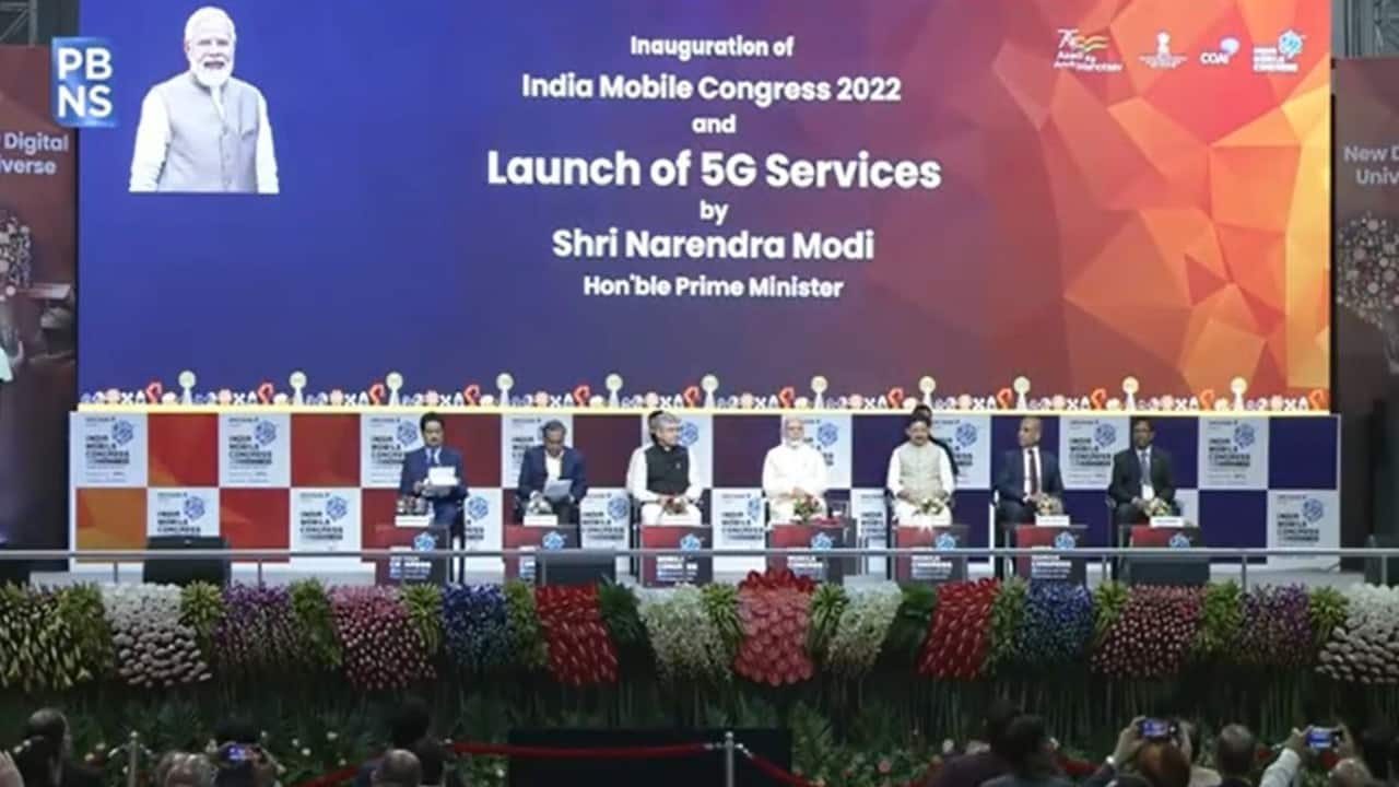
India 5G
OpenSignal: real world 5G deployment in India, market status & what happened to 5Gi?
India’s 5G deployment has advanced beyond initial spectrum acquisition and market entry announcements. By late 2025, the operational scale of three privately owned India telecom providers, alongside the impending entry of the state-owned BSNL, is facilitating a concrete transformation in nationwide connectivity for millions of users. The prevailing industry focus has shifted from initial market leadership claims to the tangible performance outcomes of 5G infrastructure. This analysis, utilizing data from OpenSignal, evaluates the practical evolution of user experience during the 4G to 5G transition in India. It examines the impact of diverse network architectures on real-world usage scenarios and identifies successful monetization strategies currently being pursued by active operators.
In the Indian 5G market, Reliance Jio holds the largest share in terms of total subscribers and 5G availability, while Bharti Airtel is a strong second, known for superior performance metrics. Vodafone Idea (Vi) entered the market this year (more below), and state-run BSNL is preparing for its commercial launch. India had nearly 400 million 5G subscriptions by the end of 2025. The total number of mobile subscribers in the country reached approximately 1.17 billion as of October 2025.
Key takeaways from OpenSignal:
- The uplift is real: Moving from 4G to 5G delivers multi-fold gains in download speeds and a more consistent, “good enough” experience.
- Architecture matters: Standalone 5G converts availability into actual usage far more effectively than Non-Standalone deployments.
- FWA stands out: Fixed Wireless Access has emerged as India’s first large-scale, commercially successful 5G monetisation story.
Vodafone Idea (Vi) commercially launched 5G services in the Indian market in March 2025, initiating deployment in Mumbai several years subsequent to its competitors, Reliance Jio and Airtel. This initial launch was followed by a phased expansion throughout the first half of 2025, extending 5G availability across key licensed circles including Delhi, Bengaluru, Chandigarh, and Patna.
Despite a later market entry, Vi subscribers transitioning from 4G to 5G connectivity are experiencing substantial performance enhancements. Opensignal data indicates a significant sixfold increase in average 5G download speeds relative to Vi’s established 4G metrics. This improvement directly addresses data-intensive applications such as high-definition (HD) video streaming, expedited application downloads, and seamless social media integration, thereby optimizing core user experiences.


Consistent Quality measures how often users experience a network that is “good enough” for everyday tasks such as video streaming, video calls, and web browsing. Across all operators, 5G users experience fewer interruptions and less performance volatility than on 4G. This reinforces that the value of 5G lies not only in peak speeds, but in delivering a more reliable day-to-day experience. While performance enhancements elucidate the intrinsic value of 5G to end-users, the sustained accessibility of these networks offers critical insights into underlying network design principles and practical service delivery.
As 5G infrastructures mature, the key performance indicator (KPI) shifts from mere geographical deployment to quantifying the actual time users can leverage the technology. This analysis is further complicated by the concurrent operation of both 5G Standalone (SA) and Non-Standalone (NSA) network architectures. Historically, Opensignal’s “5G Availability” metric quantified the proportion of time users were actively linked to a 5G network bearer. This remains a crucial measure of real-world 5G utilization. To enhance definitional clarity, this metric has been renamed “Time on 5G,” representing the percentage of time users with 5G-capable devices are actively connected to a 5G signal. It is relevant to note that numerous markets continue to heavily rely on NSA infrastructure, where devices may display a 5G signal indicator even if the primary data traffic is routed via the 4G core network.
Operators can also configure the 5G indicator to denote proximity to coverage rather than active connectivity. To address this technical nuance, Opensignal introduced a revised “5G Availability” metric in October 2025. This metric measures the total proportion of time users detect a 5G signal, irrespective of the underlying data bearer technology (4G or 5G). Collectively, these two metrics provide a comprehensive analytical framework for the 5G experience:
- 5G Availability indicates network accessibility, measuring the frequency with which users are within range of a 5G signal.
- Time on 5G indicates network utilization, measuring the frequency with which users remain actively connected to and utilizing a 5G network while engaged in data activities.
As Vi focuses on coverage expansion, Jio and Airtel have entered a more mature optimisation phase. Data from September–November 2025 highlights how network architecture – not just footprint – shapes real-world 5G usage.

The gap between these two metrics reveals how effectively operators convert theoretical access into practical, sustained usage. A small gap suggests that users can stay on 5G during everyday activity; a large gap points to frequent fallback to 4G during active sessions, even when 5G coverage exists.
Reliance Jio: Standalone efficiency
Jio converts availability into usage almost one-to-one, with 67.3% Time on 5G versus 68.1% 5G Availability. Its Standalone (SA) architecture, combined with 700 MHz spectrum for deep indoor penetration, enables devices to remain on 5G throughout active data sessions – translating coverage directly into experience.
Bharti Airtel: Non-Standalone trade-offs:
Airtel matches Jio’s reach, with 66.6% Availability, but users spend only 28.0% of their time on 5G. This reflects characteristics of its Non-Standalone (NSA) deployment, where 5G relies on a 4G anchor for control signaling. While NSA has enabled faster nationwide rollout and earlier access to 5G services, it can also lead to more frequent handovers back to 4G during mobility or sustained data use.
Vodafone Idea: Early-stage rollout:
Vi records 32.5% Availability and 9.7% Time on 5G, consistent with a network still in the early phases of deployment rather than indicating inherent performance limitations. These gaps underline why operators are increasingly focusing on densification, including the deployment of small cells and street-level infrastructure, to improve indoor coverage and reduce reliance on 4G offload.
5G adoption and financial momentum:
As the “free 5G” era fades, India’s top-tier telcos are refining their monetization playbooks. We are seeing a clear divergence in how the “Big Two” approach the market:
- Reliance Jio’s scale play: Jio continues to lead in sheer volume, projected to approach 300 million 5G subscribers by FY26. Their strategy is one of deep vertical integration bundling 5G with AI-driven services and “Cloud Phones.” This approach lowers the hardware barrier to entry while increasing “stickiness” within the Jio digital ecosystem.
- Airtel’s Quality Focus: Bharti Airtel maintains higher ARPU of ₹256 (US$2.8) compared to Jio’s ₹211.4 ($2.3). Their focus remains on high-value customers and long-term network resilience. Its acquisition of 400 MHz of spectrum from Adani Data Networks in the 26GHz signals clear intent to lead on capacity and performance, particularly in urban hotspots and industrial corridors.
FWA: The New Revenue Frontier:
One of the most consequential developments of 2025 has been the rapid rise of 5G Fixed Wireless Access (FWA). For years, fibre expansion in India was constrained by Right-of-Way challenges and high deployment costs. 5G FWA has effectively bypassed these barriers. Our data also shows that FWA offers a comparable experience to fixed line in India.
By October 2025, the total 5G FWA base – including Unlicensed Band Radio (UBR) – reached 13.18 million subscribers. Reliance Jio dominates this segment, with 10.2 million AirFiber subscribers, around four times Airtel’s 2.5 million base. A meaningful share of Jio’s growth comes from its UBR-specific offering, which alone accounts for 2.8 million subscribers.
UBR allows operators to deliver last-mile broadband using unlicensed spectrum (typically in the 5 GHz band), while relying on licensed spectrum for backhaul and control. In practice, this hybrid approach lowers deployment costs, accelerates rollouts, and reduces pressure on licensed 5G spectrum.
FWA users were consuming more than 12 times the data of mobile users last year in India – a high value service to consumers that enabled operators to monetise 5G through higher-value, tiered broadband plans and digital home bundles. This marks India’s first successful non-mobile 5G monetisation use case at scale, particularly in Tier 2 and Tier 3 cities.
BSNL’s “Made in Bharat” Entry:
Looking ahead to 2026, BSNL’s planned 5G launch introduces a distinct strategic dimension. Using an entirely indigenous telecom stack developed by C-DOT and TCS, BSNL’s rollout aligns closely with India’s Atmanirbhar Bharat ambitions.
This not only bolsters India’s “Atmanirbhar Bharat” initiative but also positions the country as a global exporter of cost-effective, end-to-end telecom solutions. BSNL has already commissioned nearly 98,000 indigenous 4G towers that are 5G-convertible, aiming for a full 5G switch shortly after.
Looking Ahead:
As investor scrutiny intensifies ahead of Jio’s anticipated IPO, the metric for success has fundamentally changed. The market is no longer asking who rolled out the fastest; it is asking who can maintain quality as data consumption nears a staggering 40 GB per user per month.
With sub-₹10,000($112)5G smartphones accelerating adoption, network stress will only increase. The next phase of India’s digital journey will be won by operators that can balance scale with consistency, and deliver a 5G experience that remains reliably “good enough” for everyday life.
How Opensignal measures real-world 5G experience:
Opensignal’s insights are based on billions of measurements collected from real users’ devices. Our metrics reflect how consumers actually experience mobile networks in everyday conditions, rather than theoretical network capability.
- 5G Availability measures the proportion of time users with a 5G device and subscription detect a 5G signal.
- Time on 5G measures the proportion of time those users are actively connected to a 5G network bearer.
- Consistent Quality assesses how often the network is “good enough” for common activities such as streaming video, video calls, and web browsing.
By combining these metrics, Opensignal captures both access to 5G and actual usage of 5G, providing a holistic view of real-world network performance.
…………………………………………………………………………………………………………………………………………………………………………………………………………………………….
5G Market Status in India:
| Operator | Overall Wireless Market Share (October 2025) | 5G Strategy & Position |
|---|---|---|
| Reliance Jio | 41.36% | Market Leader in subscriber numbers, total availability, and 5G FWA (Fixed Wireless Access) with ~85% share in FWA. Uses a Standalone (SA) 5G architecture. |
| Bharti Airtel | 33.59% | Second Largest Operator, focuses on network quality and speed performance, often leading in average download speeds in independent tests. Uses a Non-Standalone (NSA) 5G architecture. |
| Vodafone Idea (Vi) | 17.13% | Entered the 5G market later in March 2025 and is in a phased rollout. Its customers upgrading to 5G experience a significant speed increase from their 4G service. |
| BSNL | 7.90% | State-owned operator, trailing the private players and preparing to launch its 5G services. |
Key Trends
- Rapid Adoption: India has one of the fastest 5G network rollouts globally, with coverage in virtually all districts.
- Focus Shift: The competitive metric has moved from simply who launched first to delivering consistent network quality and user experience as data consumption soars (average use reached 36 GB/month).
- FWA Growth: 5G Fixed Wireless Access (FWA) is a significant growth area, with over 13 million subscribers, primarily driven by Jio’s AirFiber service.
What became of the ITU-R 5Gi standard:
It’s quite disappointing to this author that none of India’s 5G network operators have rolled out, or plan to deploy has deployed the ITU M.2150 5Gi standard in their commercial networks. The 5Gi standard was developed by Indian academic institutions (IIT Hyderabad and IIT Madras) and the Telecommunications Standards Development Society, India (TSDSI) to address India-specific needs, primarily to enhance rural 5G coverage cost-effectively through Low Mobility Large Cell (LMLC) technology. 5Gi was officially recognized by the ITU-R as a legitimate 5G RIT standard alongside the 3GPP specifications in 2020.
Industry adoption failed: Despite government encouragement and the standard’s potential benefits for rural connectivity, Indian telecom operators and global equipment vendors (like Nokia, Ericsson, and Samsung) expressed significant reservations about its mandatory adoption. The industry cited concerns about the lack of a device ecosystem, potential interoperability issues with existing global 3GPP infrastructure, and increased costs and deployment delays if they were forced to re-engineer their networks.
In practice, the 5G networks rolled out in India use equipment and technology based on the established 3GPP specifications, with no specific, separate deployment of the original 5Gi standard. Vodafone Idea (Vi) had previously indicated interest in conducting trials with 5Gi technology, but these plans did not lead to commercial deployment
References:
https://insights.opensignal.com/2025/12/5g-experience-in-india-from-rollout-to-real-world-impact/dt
Nokia’s Bell Labs to use adapted 4G and 5G access technologies for Indian space missions
Reliance Jio in talks with Tesla to deploy private 5G network for the latter’s manufacturing plant in India
LightCounting & TÉRAL RESEARCH: India RAN market is buoyant with 5G rolling out at a fast pace
Communications Minister: India to be major telecom technology exporter in 3 years with its 4G/5G technology stack
India to set up 100 labs for developing 5G apps, business models and use-cases
Adani Group to launch private 5G network services in India this year
5G in India to be launched in 2023; air traffic safety a concern; 5G for agricultural monitoring to be very useful
5G Made in India: Bharti Airtel and Tata Group partner to implement 5G in India
5G in India dependent on fiber backhaul investments
Hindu businessline: Indian telcos deployed 33,000 5G base stations in 2022
Nokia Executive: India to Have Fastest 5G Rollout in the World; 5Gi/LMLC Missing!
At long last: India enters 5G era as carriers spend $ billions but don’t support 5Gi
Bharti Airtel to launch 5G services in India this August; Reliance Jio to follow
India government wants “home-grown” 5G; BSNL and MTNL will emerge as healthy
India Telcos say private networks will kill 5G business
Vi and A5G Networks partner to enable Industry 4.0, Smart Cities in “Digital India” using 4G spectrum
India’s Production Linked Incentive (PLI) scheme for 5G equipment attracts Nokia & Ericsson
Vodafone Idea to test 5G-based smart city solutions with Larsen & Toubro in Pune, India
TSDSI’s 5G Radio Interface spec advances to final step of IMT-2020.SPECS standard
India’s TSDSI candidate IMT 2020 RIT with Low Mobility Large Cell (LMLC) for rural coverage of 5G services
ITU-R WP5D IMT 2030 Submission & Evaluation Guidelines vs 6G specs in 3GPP Release 20 & 21
India unveils Bharat 6G vision document, launches 6G research and development testbed
ABI Research: Major contributors to 3GPP; How 3GPP specs become standards
At long last: India enters 5G era as carriers spend $ billions but don’t support 5Gi
After years of 5G auction delays, India became the last major Asian economy to launch a 5G network, marking a new wave of spending by indebted Indian carriers. Prime Minister Narendra Modi made the first 5G video call on Saturday to school students to demonstrate use of the service in education. “5G is the beginning of an infinite space of opportunities,” especially for the country’s youth, he said. Well, that has yet to be proven!
Though 5G mobile technology — first introduced in South Korea three years ago — has been viewed by consumers as underwhelming so far because of a dearth of matching applications, local operators led by billionaire Mukesh Ambani’s Reliance Jio Infocomm Ltd. are betting that will change. They are counting on the nation’s 600 million-plus smartphone users to switch to the new network in due course and also on industries gearing for a digital transformation.
Carriers agreed to fork out $19 billion just two months ago for airwaves at a government auction, with Reliance’s $11 billion bid topping the list. The conglomerate proposes to invest 2 trillion rupees ($25 billion) more. Billionaire Sunil Mittal’s Bharti Airtel Ltd. and Vodafone Idea Ltd. haven’t disclosed their spending plans as yet.
While Reliance raised more than $25 billion from marquee investors in 2020 to help fund digital expansion, the need to spend big on 5G could weigh on the finances of rivals. Bharti and unprofitable Idea have a combined net debt of $37 billion, and the latter staved off bankruptcy by giving 36% of its equity to the Indian government earlier this year in lieu of back fees it couldn’t pay.
At the launch event on Saturday, Ambani said Jio’s 5G network will cover the entire country by December next year, while Mittal said Bharti Airtel plans to do so by 2024. Given the scale of spending, some experts said carriers are unlikely to undercut each other on prices once again — something that was tried in 2016 when Jio entered the market by offering free calls and cheap 4G data plans, which ended up putting some rivals out of business.
“They will likely provide 5G services to those segments of the market that are willing to pay higher and try and recover as much as possible before making it available to others,” said Rajat Kathuria, a senior visiting professor at the Indian Council for Research on International Economic Relations in New Delhi.
5G’s long road to India has been dogged by several controversies. The main one was about how secure Chinese equipment is — a crucial issue for a country engaged in a border conflict with its northern neighbor. Last year, carriers decided to avoid Chinese vendors such as Huawei Technologies Co. and ZTE Corp., and opted instead to tie up with makers like Ericsson AB, Nokia Oyj and Samsung Electronics Co., potentially adding to their costs.
“India may have started a little late, but we’ll finish first by rolling out 5G services that are of higher quality and more affordable,” Ambani said at the launch event. The technology can bring affordable, superior education and skill development to ordinary Indians and deliver high-quality healthcare to rural and remote areas, he said.
Despite India’s TSDSI getting 5Gi (5G for India or Low Mobility Large Cell) included in ITU M.2150 (previously known as IMT 2020), no Indian carrier has announced support of it. That is a major disappointment for TSDSI. Please refer to the numerous references below.
Offering low latency (that does not meet ITU-R M.2410 URLLC performance requirements) and data speeds about 100 times faster than 4G (depending how close your 5G endpoint is to the cell tower or small cell), the technology may someday have the potential to enable a variety of advanced applications such as holograms, 3D avatars of people in metaverses and telemedicine, in which near-instantaneous transmission of video and data would allow surgeons to operate remotely using a robotic scalpel. So far, such applications have been too slow to evolve. For average users, 5G has mostly meant faster video games and content streaming.
To capitalize on 5G, China has been rolling out smartphone apps and industrial projects such as super high-definition live streaming, remote manufacturing, virtual reality and robotic surgery arms. The country’s three state-owned carriers have introduced more than 25,000 such applications, according to a news article posted by the State Council on its website in August. In South Korea, despite mobile operators’ efforts to come up with killer apps, average revenue per person has only climbed slightly since the 4G era.
In India’s race to roll out 5G, the only winner to emerge so far has been the government: The airwave auction was set to raise a record amount, Telecom Minister Ashwini Vaishnaw said in July.
Proceeds from the spectrum auction could provide a big financial boost to Modi’s administration, which has been seeking to tame inflation and rein in fiscal deficits as economists warn of a looming global recession.
References:
https://ieeetv.ieee.org/2020-5g-world-forum-keynote-radha-krishna-ganti
https://tsdsi.in/wp-content/uploads/2020/02/LMLC_ver1_RIT-Prof-Ganti.pdf
TSDSI’s 5G Radio Interface spec advances to final step of IMT-2020.SPECS standard
India lagging in 5G unless spectrum prices decrease & 5Gi standard debate is settled
Jio and Airtel against 5Gi standard; 2 GHz of mid-band needed for India 5G demand
India’s Success in 5G Standards; IIT Hyderabad & WiSig Networks Initiatives
Bharti Airtel working with partners to enable 5G use cases in India
Bharti Airtel said that it is engaging new partners to enable 5G use cases for various consumer and enterprise use cases in India. It will also start a campaign to educate users about their next 5G smartphone to ensure if they can get the best experience with support to all relevant bands.
A handset to support all possibilities of 5G is very important, Bharti Airtel’s chief technology officer Randeep Sekhon told ET. Airtel will come out with a campaign for users who want to buy 5G handsets informing them about various checks of their particular handsets to make sure the handset works well in India across not just 5G but various other bands and carrier aggregation. “This is important when you choose a 5G handset to get the best experience,” he said.
The Sunil Mittal-led telecom operator had recently urged the India Department of Telecommunications to bring uniform guidelines to develop the 5G smartphone ecosystem. It recommended that any new 5G handset sold in India must support all existing bands in India for 5G, including the mmWave bands.
Indian telecom operators have spectrum in the 2G, 3G and 4G bands which can be refarmed and used for 5G NSA or 5G SA and also use Dynamic Spectrum Sharing (DSS) for fast deployment. They want handset brands to support all existing spectrum bands like 1800/2100/2300 MHz and sub-GHz bands 800/900 Mhz.
The telecom operator said that it successfully conducted a cloud gaming session on its 5G trial network in Manesar using the 3.5GHz spectrum band. Sekhon said that “immersive entertainment” will be another major consumer use case of 5G. “But, for A/R and V/R, content needs to be created and be personalized at the edge. We are seeing how we can make it real.”
Airtel is currently using the 3.5 GHz spectrum band for 5G trials in Delhi-NCR and Mumbai. Sekhon said that the telco hasn’t started 5G trials using mmwave band. “As and when we will get equipment, we will try that too. 3.5 GHz anchored with traditional 4G bands are currently being used for trials.”
“For the B2B, industry 4.0, high speed, high latency and mass concurrency around IoT cloud and 5G are required.. We are working with many of our industry customers on creating fir infra, FMCG, factory, mining. This will be relevant,” Sekhon added.
The CTO said that telecom operators can’t do everything by themselves and their main focus is to build the best infrastructure to enable partners. Airtel, he said, will have various partners to enable 5G use cases like education, e health and for industries.
“Some partnerships are for initial 5G trials and some will for massifying the roll out. The 5G real experience will happen when all stakeholders ecosystem partners are available,” Sekhon said.

India’s DoT WPC allocates 5G trial spectrum in 3.5 Ghz, 26 Ghz and 700 Mhz bands
In the seemingly never-ending saga of “5G delayed in India,” the Department of Telecom (DoT) has allotted 5G trial spectrum in the 700 Mhz, 3.5 Ghz and 26 Ghz bands. That paves the way for the Big 3 — Reliance Jio, Bharti Airtel and Vodafone Idea (Vi) to partner with non-Chinese network vendors and develop India-relevant use cases for 5G networks (forget about URLLC which doesn’t meet 5G performance requirements in 3GPP Release 16 or IMT 2020 RITs).
The DoT’s wireless planning & coordination (WPC) wing late Thursday evening allotted “100, 800 and 10 units of experimental 5G airwaves to the Big 3 telcos in the 3.5 Ghz, 26 Ghz and 700 Mhz bands respectively,” a senior telco executive told ET. The 5G trial airwaves have been allocated for six months, he added.
Earlier this month, India’s DoT said telcos would be given experimental airwaves in mid-band (3.2-3.67 Ghz), sub-Ghz (700 Mhz) and mmWave band (26 Ghz) to run 5G trials for six months. So far, only mid-band spectrum in the 3.3-3.6 Ghz bands have been earmarked by the government for 5G services. The department had also said that telcos would also be allowed to use their own airwaves in the 800 Mhz, 900 Mhz, 1800 Mhz and 2500 Mhz bands to conduct 5G trials.
Huawei and ZTE were missing from the original list of applications from the Indian telcos that were approved by the government earlier this month, sending a clear signal that the two Chinese network equipment vendors would not be part of India’s 5G deployments as well.
Allotment of 5G trial spectrum is particularly crucial for Jio and Airtel, who already have 5G-ready networks and have recently bulked up on crucial airwaves in the recent auction to cater to the surge in data usage amid Covid and also future-proof themselves ahead of 5G rollouts.
DoT’s decision also marks the first official allocation of 5G trial spectrum in the coveted 26 Ghz millimeter wave (mmWave) band that ranges from 24.25-to 28.5 Ghz frequencies. Telcos have repeatedly underlined the criticality of the 26 Ghz mm wave band for bolstering the 5G business case, without which deployment costs of fifth- generation fast wireless broadband networks could jump several-fold and make 5G services unaffordable to consumers in India.
Industry executives said the latest allotment of experimental 5G airwaves is also set to pave the way for inclusion of the coveted 26 Ghz mmWave band and mid-band 5G spectrum (read: 3.3-3.67 Ghz) in the updated National Frequency Allocation Plan (NFAP-2021) — a key spectrum policy document that is undergoing revision. This is aimed to underline the government’s plans to go for a comprehensive auction of multiple 5G bands. DoT is yet to schedule a 5G spectrum sale.
It, though, is set to send a referral to the Telecom Regulatory Authority of India (Trai) to suggest reserve prices for all spectrum bands cleared for 5G trials, including 26 Ghz, 3.3-3.67 Ghz and 700 Mhz in the run up to the next auction. This could lead to Trai cutting the earlier base prices of the premium-sub-Ghz 700 Mhz band that went unsold for the second auction in succession in March as well as mid-band 5G spectrum that have been termed by telcos as exorbitant.
The DoT is also likely to ask the regulator to set a base price for the 600 Mhz sub-Ghz band, which has not been auctioned previously.
References:
India ramps up supply chain for 5G service launch in 2021 pending spectrum auction
Economic Times: India’s big bet on 5G in 2021 starts with 5G spectrum auction
India telecom revenue to slow through March 2021; 5G spectrum auction delayed yet again
At long last: India Telecom Minister gives go ahead for 5G trials
India’s Success in 5G Standards; IIT Hyderabad & WiSig Networks Initiatives
by Prof. Kiran Kuchi, PhD & Dean of Research at Indian Institute of Technology Hyderabad (IITH) -edited by Alan J Weissberger, ScD EE
The development of 5G happens through a global forum called the 3rd Generation Partnership Project (3GPP). It’s a partnership between seven global Standards Development Organizations (SDOs) of which Telecommunications Standards Development Society, India (TSDSI) is a member. 3GPP kickstarted the 5G project in 2016 where we made substantial contributions to three successive releases of 5G specifications to date. IITH primarily led the efforts with significant support from CEWiT, IITM, and other Indian corporations (Tejas Networks and Reliance Jio are our major industry partners) with well over 300 technical documents submitted to date.
These sustained efforts led to the incorporation of several innovations introduced into the global 5G standards. One significant contribution that stands out is the introduction of a new transmit waveform, the only new waveform that is adopted in 5G, which is a generational change.
Both 4G and 5G adopted a waveform technology called OFDM (Orthogonal Frequency Division Multiplexing) that is quite suitable for the downlink transmission (that is the link between a base station (BS) and user equipment (UE)) but not so well suitable for the reverse link (that is the link between UE and BS). The limitations of OFDM owes to low-power efficiency (of about 10%). Prof Kuchi has designed a new waveform called “pi/2 BPSK with spectrum shaping” that provides close to 100% power efficiency and yet retains all the other advantages offered by OFDM.
This new transmit waveform allows the power amplifier in the UE to operate near its saturation level thus delivering a 3-4fold increase in the transmission power, and a hardware cost similar to that of OFDM. The overall gain in the cell range compared to OFDM will be at least twofold, hence this became a driver behind the design of the large cell 5G concept.
This indigenous waveform technology is developed for over a decade and is covered by a family of patents developed by IITH and CEWiT. There are well over 100 patents filed by IITH and WiSig to date. These patents will likely become the backbone of our indigenous 5G ecosystem. India’s 5G at ITU There are two parallel tracks that India took during the 5G development. The first effort is the aforementioned contributions to the 3GPP-based 5G standard, and our second noteworthy contribution is through TSDSI and the ITU (International Telecommunication Union). The second effort is led by IITM on the ITU front with significant backing and support from IITH, CEWiT (and Indian Industry such as Tejas networks, Reliance Jio).
ITU is a United Nations body that specifies requirements and radio standards for 5G known generically as IMT 2020. ITU-R WP5D had adopted India’s proposed Low-Mobility-Large-Cell (LMLC) use case as a mandatory 5G requirement in 2017. This requirement was adopted by ITU-R WP5D mainly as a result of sustained effort by the Indian entities through the Department of Telecommunications (DoT) to address the unique Indian rural broadband deployment scenario. Several countries supported this use case as they saw a similar need in their jurisdictions as well. TSDSI took this opportunity to develop the so-called LMLC based 5G technology that is a modification of 3GPP-based 5G specification.
This indigenously developed standard designated as 5Gi will deliver ultra-fast, low-latency mobile internet and next-generation IoT services in both cellular and mm-wave spectral bands that are common to all 5G candidate standards and adds “pi/2 BPSK with spectrum shaping waveform” as a mandatory technological enhancement that can provide broadband connectivity to rural users using ultra-long range cell sites.
This enhancement will ensure that 100% of India’s villages are covered from towers located at panchayat villages, whereas nearly a third of such villages would be out of coverage otherwise. Both 5G and 5Gi are fully compatible and interoperable systems that are being leveraged for the upcoming deployments in India. Adoption of the LMLC based 5G standards in India will enable India to leap forward in the 5G space, with key innovations introduced by Indian entities accepted as part of global wireless standards for the first time. The nation stands to gain enormously both in achieving the required 5G penetration in rural and urban areas as well as in nurturing the nascent Indian R&D ecosystem to make a global impact. The current national efforts are aligned with the national digital communication policy that promotes innovation, equipment design, and manufacturing out of India for the world market.
MeitY has been funding our wireless research for the past 10 years and these efforts have led to the development of larger wireless programs. More recently, the DoT (India Dept of Telecom) has sanctioned the “Indigenous 5G Testbed” program with a project outlay of 224 crores to IITH, IITM, CEWiT, IITK, IITB, IISc, and SAMEER.
This 3-year program, already close to completion, started yielding results in the form of prototype base stations, CPE/UE and NB-IoT chipsets. IITH stands out with major contributions to key 5G technologies such as cloud RAN base station with massive MIMO capability and cellular NB-IoT chipset for connecting sensors and meters to the internet. We are gearing towards full-fledged demonstration and field trials.
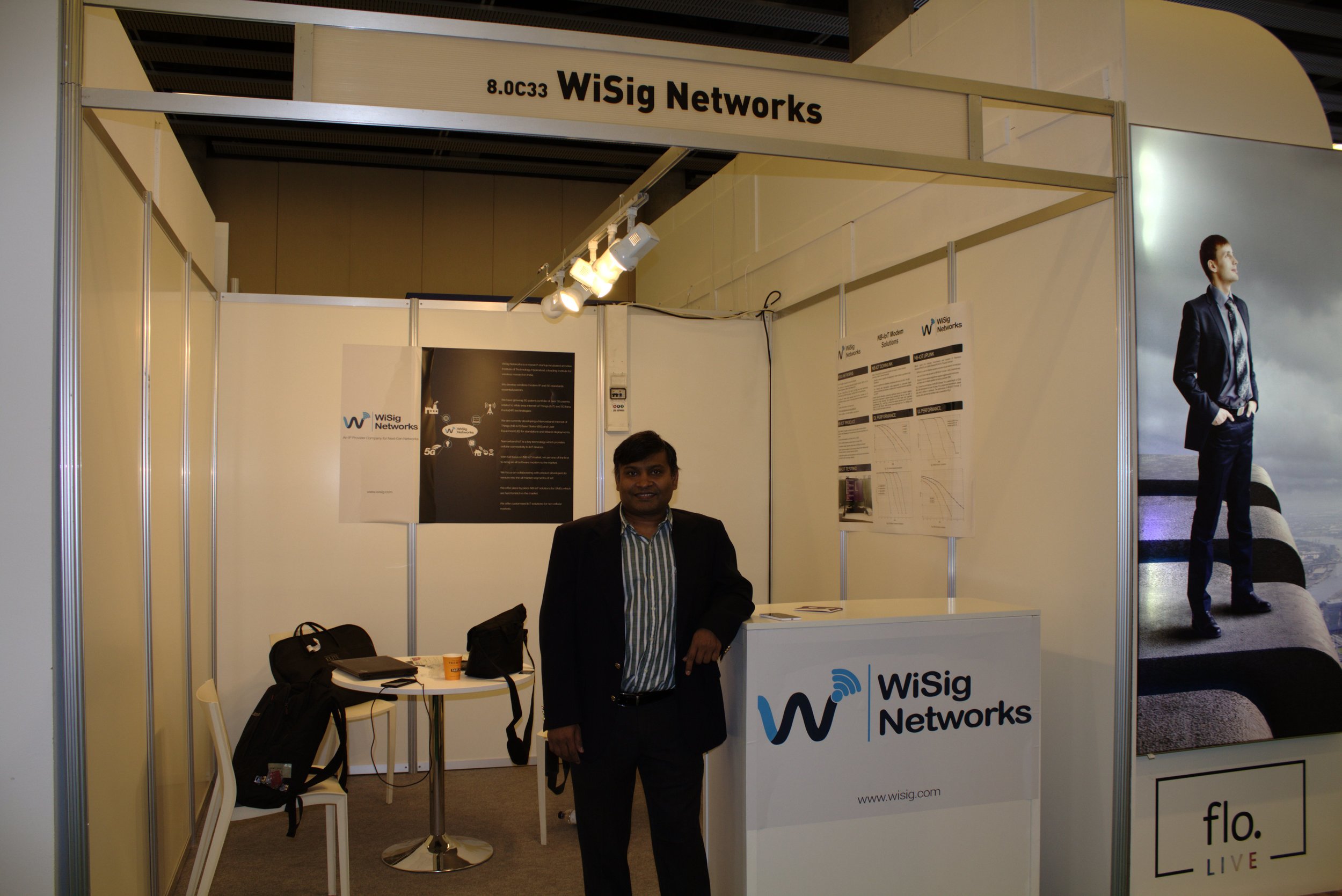
An upcoming player in the 5G space WiSig Networks (WiSig) is a 5G start-up incubated at the IITH tech incubator (i-tic foundation). WiSig has developed a 5G radio access network (5G-RAN) based on an emerging technology called O-RAN (Open-Radio-Access Network), that is being touted as the next major disruptor in the 5G landscape. This technology allows rapid deployment of low-cost, software upgradable 5G base stations in significantly higher volumes and larger densities than the current 4G network.
O-RAN is a disaggregated 4G/5G base station based on open interfaces and general purpose hardware. It is being defined by the O-RAN alliance, TIP Open RAN project and ONF SD-RAN v1.0 Software Platform for Open RAN.
Some operators have initiated the deployment of O-RAN based software-defined network and virtualization networks that enable self-organization, low operational cost and ease of introduction of new features and service upgrades. New 5G use cases can be introduced rapidly on the fly using software upgrades as opposed to costly and time-consuming hardware development cycles. WiSig has created commercial grade IP in this space and is well on track to carry out one of India’s first O-RAN compliant demonstrations of a software defined 5G massive MIMO base station. Overall, WiSig is well on its path to deliver 5G RAN intellectual property components to the global 5G supply chain.
LMLC based 5G technology is a modification of 3GPP-based 5G New Radio (NR) specification. This indigenously developed LMLC ITU-R standard, designated as 5Gi, will deliver ultra-fast, low-latency mobile internet and next-generation IoT services in both cellular and mm-wave spectral bands that are common to all 5G candidate standards and adds “pi/2 BPSK with spectrum shaping waveform” as a mandatory technological enhancement that can provide broadband connectivity to rural users using ultra-long range cell sites.
In contrast to high-speed mobile broadband, a vast number of IoT applications requires few bits to be exchanged with the internet intermittently. The key considerations of these kind of IoT devices are that they are ultra-low-cost and have a long battery life – up to 10 years. Narrowband IoT (NB-IoT) (Belongs to the 5G family of technologies is well suited for this purpose and is quietly emerging as a killer application for lowbit rate IoT applications. IITH and WiSig joined hands in commercializing a NB-IoT SoC (System on a Chip) that was successfully taped out in Q1 2021.
The chip is named “Koala” after an animal indigenous to Australia that sleeps about 20 hours a day – typical behavior of the NB-IoT modem.
Given that this is the first time a standards compliant cellular modem is designed in India and that both the software and hardware that goes into the chip is developed indigenously, this chip should preferably be leveraged to serve the security needs of critical national IoT infrastructure.
In summary, the investments made by Meity and DoT on 5G research have started to bear fruit in delivering the basic technological components and sub-systems required to build 5G. The time is ripe for the Government to nurture domestic design and manufacturing of 5G equipment. The country has enough talent and the technological depth required to support a domestic 5G ecosystem. With the right kind of policy support, then India is likely to see a 5G/IoT domestic manufacturing revolution within this decade. IITH will continue to play a pivotal role in shaping the 5G ecosystem not only in India but globally as well.
About Kiran Kumar Kuchi, PhD:
Kiran is a Professor Department of Electrical Engineering IIT-Hyderabad (IITH) and Dean of Research. He also started WiSig Networks that has been incubated at IITH. He received PhD and MS degrees in Electrical Engineering from the University of Texas at Arlington, TX. His current projects include: Cloud radio, Heterogeneous networks (HeNets), Next generation wireless test-bed development.
References:
https://pcr.iith.ac.in/Kiriith-Issue-6,April,20215GandNext-GenCommunicationTechnologies.pdf
Ericsson ConsumerLab report highlights + 40M 5G India smartphone users forecast
A study conducted by Ericsson ConsumerLab has the following key findings:
1. Consumer intent to upgrade to 5G accelerates despite the pandemic. At least 300 million smartphone users could take up 5G in 2021. By the end of 2020, 22 percent more smartphone users with 5G-ready smartphones could have adopted 5G if knowledge gaps had been addressed.
2. 5G triggers changes in usage behavior, starts to displace Wi-Fi. 5G users spend two hours more per week using cloud gaming and one hour more on augmented reality (AR) apps compared to 4G users. 20 percent say they have decreased their usage of Wi-Fi after upgrading.
3. Indoor 5G coverage more important for consumers. 5G early adopters rate indoor 5G coverage as two times more important than speed or battery life in driving satisfaction.
4. Early adopters are pleased with 5G speeds but expect more innovation. Seventy percent are dissatisfied with the availability of innovative services and expect new applications making use of 5G.
5. Consumers value 5G plans bundled with digital services and are willing to pay 20–30 percent more. However, two-thirds of use cases highly valued by consumers have not yet been commercialized.
Ericsson’s ConsumerLab insight report, is claimed to be the biggest ever 5G consumer study, covering opinions of 1.3 billion consumers and 220 million 5G users, to uncover the key trends that are influencing the adoption, usage and perception of consumers towards 5G, and suggest five important steps service providers can take to meet consumer expectations now and in the future.
Image Credit: Reuters
The report suggests five ways that service providers can meet consumer expectations and improve their 5G experience, now and in the future:
1. Enhance the value: address the knowledge gap to educate and better market the value of 5G.
2. Consumers expect the quality of indoor and outdoor coverage to be consistent.
3. Adapt to network requirements of new services enabled by 5G.
4. Focus on the jobs consumers want 5G to do, to envision new use cases.
5. Go beyond just showcases: accelerate the commercialization of existing and new use cases
The study revealed that at least 40 million smartphone users are likely to be 5G subscribers in the first year of it being introduced in India. The study further suggests that users are willing to pay up to 50 percent more for 5G plans if they are bundled with digital services.
According to the report, 67 percent of users in India are eager to upgrade to 5G once it is available, which is an increase of 14 percent over 2019. Reportedly, seven out of 10 potential early adopters expect higher speeds from 5G, and six out of 10 expect “pricing innovation from Communication Service Providers”, meaning 5G data will be used to transfer media from one device to another.
The report suggests that more than one-third of urban internet users would prefer using 5G home broadband instead of the existing fixed home wireline broadband. The report further reveals users of 5G-ready smartphones in India expect to spend more time on enhanced video streaming and multiplayer mobile gaming. Ericsson predicts India residence will be spending 7.5 to 8 hours a week on iPhone XR 5G apps by 2025.
……………………………………………………………………………………………………………………………………………..
References:
https://www.ericsson.com/en/reports-and-papers/consumerlab/reports/five-ways-to-a-better-5g
Ambani: Reliance Jio to deploy 5G network in second half of 2021
Reliance Jio today announced that it will roll-out 5G services in India in the second half of 2021. The announcement was made by the company’s CEO, Mukesh Ambani (Asia’s richest man) at the fourth annual (online this year due to COVID-19) of the India Mobile Congress.
Ambani revealed that the company plans to implement 5G service in the second half of 2021, while restating that the 5G network by the company will be built indigenously. Jio is likely to be the first service provider to bring the technology to the country. It’s believed to be based on Open RAN technology, but that has yet to be confirmed by Jio.
“India is today among the best digitally connected nations in the world. In order to maintain this lead, policy steps are needed to accelerate the early rollout of 5G, and to make it affordable and available everywhere. I assure you that Jio will pioneer the 5G Revolution in India in the second half of 2021. It will be powered by the indigenous-developed network, hardware and technology components.”
Jio has developed its own 5G solution, which it hopes to sell in different countries after deploying it in its own network. Jio Platforms, with over 20 startup partners, is building capabilities in artificial intelligence (AI), cloud computing, big data, machine learning and blockchain. Jio Platforms raised funding of more than $20 billion earlier this year. Several firms, including Qualcomm, Google and Facebook, invested in the company.
“Jio’s 5G service will be a testimony to your inspiring vision of Atma Nirbhar Bharat. I can say with utmost confidence that 5G will enable India to not only participate in the Fourth Industrial Revolution but also to lead it.”
![]()
“The Indian economy will not only bounce back but will also grow with unprecedented acceleration. India can — and India will — prove cynics wrong by becoming a $5 trillion economy. It will be a More Equal India… With increased incomes, increased employment, and improved quality of life for 1 billion Indians at the Middle and Bottom of the Economic Pyramid.”
You can watch a video of Ambani’s speech here along with news reporter commentary.
Earlier this year, Qualcomm had announced that it was working with Jio Platforms and its wholly owned subsidiary, Radisys Corporation, to develop open and interoperable interface compliant architecture based 5G solutions with a virtualized RAN. The two companies had achieved the 1Gbit/s milestone on Jio’s 5G New Radio (NR) software.
While Jio has been asking the government to expedite the 5G spectrum auction, the other private telcos, Bharti Airtel and Vodafone Idea, believe India is not yet ready for 5G technology. In particular, Bharti Airtel’s chairman Sunil Mittal claiming that the rollout of 5G technology in India will take another two-three years. Mittal has said that the next generation of mobile technology will need more time to be rolled out across the country. Airtel’s decision makers, including its chief executive, Gopal Vittal, has said in the past that the ecosystem for 5G is underdeveloped and that spectrum is expensive.
Ambani concluded his address saying, ” We are about to step into a glorious decade of the India story, with the Digital India Mission playing the role of the principal accelerator. Nothing can stop India’s rise, not even COVID-19. This is our chance to create history.”
References:
https://www.lightreading.com/asia/indias-jio-to-launch-5g-in-2021/d/d-id/765966?
India’s Tumultuous Telecom Market: Government vs the Telcos
by MG Arun, India Today
Ten years after the Indian telecom was rattled by the 2G spectrum scam and the Supreme Court cancelled 122 licences issued by the UPA government in 2008, the sector is witnessing another upheaval. This time, the apex court has stepped in to ensure that telcos Bharti Airtel, Vodafone Idea and Tata Teleservices pay up over Rs 1 lakh crore in revenue share the government claims they owe in return for acquiring licences and spectrum. The three companies are widely referred to as the ‘incumbent’ players, since the other major operator, Reliance Jio, entered the market only in 2016. According to the Department of Telecommunications (DoT), which issues the licences, the three incumbents owe the government Rs 35,600 crore, Rs 53,038 crore and about Rs 14,000 crore, respectively.
On February 17, three days after the Supreme Court pulled up telcos for not abiding by its January 16 order to clear the dues, Vodafone Idea made a Rs 2,500 crore part-payment to the DoT, with the assurance that it will pay another Rs 1,000 crore by February 21. Bharti Airtel said it had paid Rs 10,000 crore to the DoT while Tata Teleservices paid Rs 2,197 crore.
While the telcos have sought relief from the hefty payments, Vodafone Idea‘s case is particularly complicated, with the court rejecting its plea that the DoT be directed not to invoke the company’s bank guarantees-reportedly about Rs 2,500 crore-to recover dues. “I hope good sense prevails over the government that if it encashes the guarantees, the banks will pay, but the company will go down,” Vodafone Idea’s counsel Mukul Rohatgi told a TV channel.
Industry observers say if Vodafone Idea shuts down, the consequences will be drastic. “It will be a terrible thing for the economy, the banking system, the telecom industry and its customers, suppliers and digital partners,” says a telecom official, requesting anonymity. “Unlike airlines, where the supply breach caused by the closure of, say, Jet Airways could be filled by other players, in telecom, capacity cannot be replaced, including the enormous physical infrastructure. In such cases, the executive should wield its powers and step in to save the operator.”
The industry expects the government to allow it an extended moratorium to make the payments, to redefine Adjusted Gross Revenue (AGR), or even waive interest and penalties, and to stick to the principal amount to be paid. The incumbents and the DoT have been waging a legal battle for around 15 years. The crisis points to ambiguities in policy, which have not only caused confusion, but also left loopholes for telcos to exploit. The government’s handling of the telecom sector has also come under question. What was a sunrise industry now sees players, except Reliance Jio, battling for survival. It all threatens to end in a duopoly that could send tariffs skyrocketing.
TROUBLED HISTORY
The telecom sector was liberalised under the National Telecom Policy, 1994, paving the way for the entry of private players. For a fixed fee, licences were issued in various categories-unified licence, which allowed a firm to offer both wireless and wireline services; licences to Internet Service Providers (ISPs); and licences to provide passive infrastructure, such as towers and fibre. In 1999, the NDA government gave licensees the option to migrate to the revenue-sharing fee model.
As per the model, telecom operators were to share a percentage of their AGR with the government as annual licence fee and spectrum usage charges. The licence fee was pegged at 8 per cent of AGR while the spectrum usage charges were fixed at 3-5 per cent. According to Clause 19.1 of the Draft Licence Agreement, gross revenue included installation charges, revenue on account of interest, dividend, value-added services and so on. Calculated on this basis, AGR excluded certain charges, such as the Interconnection Usage Charge (IUC) and roaming revenues that are passed on to other operators.
While the DoT says it is following the definition of AGR as per the licence agreement, industry sources claim the definition of AGR in the licence conditions underwent revisions regarding the applicable rates for licence fee and spectrum usage charge. While operators wanted to be charged on the basis of their core business, involving use of the spectrum allotted, the DoT said the definition of AGR includes other items, such as dividend, interest, capital gains on sales of assets and securities and gains from foreign exchange fluctuations. In 2001, the Association of Basic Telecom Operators submitted to the government that non-operational income should not be included while computing AGR. However, in 2002-2003, the DoT demanded revenue share as per the Draft Licence Agreement, following which operators approached the Telecom Disputes Settlement and Appellate Tribunal (TDSAT).
A long-drawn-out legal battle followed. Around the same time, the telcos stopped paying their revenue share on the disputed part of the AGR. Operators argued that taxes and levies in India were among the highest in the world and appealed to the government not to press for payment of AGR-based dues. The industry’s contention is that it pays the government Rs 30 for every Rs 100 earned, in the form of levies and taxes. GST is at 18 per cent, and the industry has been demanding that the licence fee be reduced to 3 per cent, and the Universal Service Obligation Fund (USOF) charge to 3 per cent from the current 5 per cent. USOF was created in 2002 to expand internet and mobile connectivity in rural areas. In August 2019, the Cellular Operators Association of India (COAI) alleged that half the funds raised by USOF between 2002-03 and 2018-19 remained unutilised.
In 2015, the TDSAT ruled that AGR includes all receipts except capital receipts and revenue from non-core sources. But on October 24, 2019, the Supreme Court set aside that order and upheld the DoT’s definition of AGR. The incumbents approached the court for a review, but the plea was rejected on January 16 this year. However, the Supreme Court agreed, on January 21, to take up a modification plea filed by the telcos, seeking to negotiate a ‘sustainable payment schedule’. This followed the Union cabinet’s decision on November 20, 2019, that telcos be given a two-year moratorium on payments.
However, on February 14 this year, the Supreme Court slammed the telcos over unpaid dues and warned of contempt proceedings if they did not pay up by March 17. “The companies have violated the order passed by this court in pith and substance,” said the court. “In spite of the dismissal of the review application, they have not deposited any amount so far.” Following the Supreme Court rap, the DoT asked the telcos to pay the AGR dues by the end of day on February 14.
As per reports, the original disputed amount of about Rs 23,000 crore snowballed to the present figure of close to Rs 1.5 lakh crore as the DoT contended that the entire dues accumulated over the past 15 years be paid with interest and penalty.
The Supreme Court was of the view that telecom players benefited immensely from the DoT’s formula of AGR calculation. In its October 24, 2019, order, the court said the “revenue-sharing package turned out to be very beneficial to the telecom service providers, which is evident from the continuing rise in the gross revenue”. Gross revenues earned by telecom service providers stood at Rs 4,855 crore in 2004, Rs 89,108 crore by 2007, and subsequently touched Rs 2,37,676 crore in 2015, said the court.
SIGNALS TURN RED
“The industry is reeling from the Supreme Court decision on AGR. It has further aggravated the already precarious financial position of operators,” says Rajan Mathews, director general of COAI. “The ball is now firmly in the government’s court to fix the vexatious AGR problem, by either eliminating it altogether or redefining it along the lines recommended by the Telecom Regulatory Authority of India and the industry, as well as reduce the licence fee and spectrum usage charge to 3 per cent and 1 per cent, respectively. We believe AGR is an anachronism in a day when operators have paid for spectrum and licences upfront.”
As of January, TRAI pegs Reliance Jio as the largest telecom player, with 369 million mobile subscribers, followed by Vodafone Idea (336 million) and Bharti Airtel (327 million). ‘The increase in Jio’s subscriber base is largely at the cost of the fall in Vodafone Idea‘s subscriber base,’ says a report by India Ratings and Research. While a Vodafone Idea spokesperson refused to comment, company sources said the board had assessed the company could pay up Rs 3,500 crore without delay, of which Rs 2,500 crore was paid on February 17. Vodafone Idea‘s assessment of its dues to the government is “significantly different” from the government’s claim, the source says. For part payments of dues, the company can dip into its cash reserves without affecting its working capital needs. Also, the Indian subsidiary can ask the parent Vodafone Plc to pitch in with Rs 8,000 crore, the source says. The proposed sale of Indus Towers, a telecom infrastructure firm jointly promoted by the Bharti Group and Vodafone Group, would also help.
In a February 17 letter to member (finance), DoT, Bharti Airtel director-legal Vidyut Gulati said that of the Rs 10,000 crore paid, Rs 9,500 crore was on behalf of Bharti Airtel and Rs 500 crore on behalf of its subsidiary, Bharti Hexacom. ‘We are in the process of completing the self-assessment exercise expeditiously and will duly make the balance payment upon completion of the same, before the next hearing in the Supreme Court,’ says the letter, which india today has seen. While a Bharti Airtel spokesperson declined comment on the AGR matter, a mail sent to Tata Teleservices went unanswered till the time of going to press.
The Supreme Court’s October 2019 directive hit the incumbent telcos hard. The year-to-date losses for Vodafone Idea, Bharti Airtel and Tata Teleservices in FY2019-20 stand at Rs 62,233.8 crore, Rs 26,946 crore and Rs 2,840 crore, respectively. Vodafone Plc has already spent over $17 billion (around Rs 1.2 lakh crore) to buy out Hutch and Essar’s stake in Vodafone Essar between 2007 and 2012, and injected several billions of dollars more to acquire spectrum and build infrastructure. Effective December 1, 2019, Reliance Jio, Vodafone Idea and Bharti Airtel announced tariff hikes, for the first time in five years. According to India Ratings and Research: ‘The average revenue per user (ARPU) reported by telcos has started showing signs of recovery in the last two-three quarters. The recent tariff hikes are likely to support the increase in ARPU over the next few quarters.’
Even if Vodafone Idea tides over the AGR crisis by, say, delayed annual payments over the long term, its weak balance sheet makes it vulnerable, as per an SBI Caps note, to incremental regulatory changes. In a three-player market, that could be a reason for TRAI to go soft on it. ‘But the moment Indian telecom shapes up as a duopoly, the regulator may start perceiving telcos differently. Price hikes, pricing power, spectrum pricing-all…may see the regulator taking a tougher stand,’ the note says. While some analysts foresee a Reliance Jio–Bharti Airtel duopoly and higher tariffs, Vodafone Idea is looking to stay in the fight. “There is hope of some relief in terms of staggered payments [of dues],” says a company official. But the options seem to be running out for the British telco that had entered India betting on its high growth potential.
India’s TSDSI candidate IMT 2020 RIT with Low Mobility Large Cell (LMLC) for rural coverage of 5G services
India’s telecom standards organization TSDSI has submitted its candidate IMT-2020 Radio Interface Technology (RIT) to the IMT-2020 evaluation at the ITU-R WP 5D meeting #32 being held in Buzios, Brazil from 9 July 2019 to 17 July 2019. TSDSI’s IMT 2020 submission is one of five candidate RIT proposals- see NOTE at bottom of this article for more information.
TSDSI’s RIT is described in document ITU-R WP5D-AR Contribution 770. This RIT has been developed to address the rural requirements by enabling the implementation of Low Mobility Large Cell (LMLC), particularly with emphasis on low-cost rural coverage of 5G wireless network services. TSDSI believes that this RIT will also help to meet the rural requirements of other developing countries. This author agrees!
TSDSI proposal on Low Mobility Large Cell (LMLC) configuration has been included as a mandatory test configuration under the Rural eMBB (enhanced Mobile BroadBand) test environment in IMT 2020 Technical Performance Requirements (TPR) in ITU-R with an enhanced Inter Sire Distance (ISD) of 6 km. Incorporation of LMLC in IMT2020 will help address the requirements of typical Indian rural settings and will be a key enabler for bridging the rural-urban divide with 5G rollouts.
–>The Indian administration (ITU member country) extends its support to the RIT of TSDSI and solicits the support of ITU Member States to support this proposal.
Indian wireless network operators, including Reliance Jio Infocomm Ltd, have expressed interest in LMLC.
About TSDSI:
*TSDSI is a Standards development organization similar to ETSI, SRIB, ATIS, CCSA, TTA, TTC, etc.
*TSDSI is an Organisational Partner of 3GPP and oneM2M, an Associate member of ITU-R and ITU-T and a member of GSC.
*TSDSI delegations have been actively participating and contributing in Standards development Working Groups in all these forums.
*TSDSI has formal affiliations (MoUs/Agreements) with – ETSI, 5GIA, ATSC, BIF, CCICI, GCF, IEEE-SA, TIA, TAICs, TTA, WWRF, ARIB, ATIS, CCSA, TTC
*TSDSI conducts several joint activities – projects, workshops, conferences etc. with its affiliates
*TSDSI’s operating procedures have been derived based on best practices being followed by similar Global SDOs.
*TSDSI Rules & Regulations, Working Procedures and IPR Policy are all transparent and available on our website – http://www.tsdsi.in. A brief perusal will show the similarity with the processes and policies followed by other SDOs.
*TSDSI strictly follows the Rules and Procedures. It provides an open, transparent and collaborative platform for its members to participate and contribute in the development of Standards with a special focus on India Specific Requirements and Indian Innovations. The governance model is also very inclusive, open and transparent with fresh elections being conducted for all positions every 2 years.
Submitted by: Chair TSDSI , Vice Chair TSDSI and DG TSDSI
http://www.tsdsi.in
………………………………………………………………………………………………………………………………………….
Kiran Kumar Kuchi, a professor at IIT Hyderabad is building a 5G testbed there. The system will exceed IMT 2020 5G performance requirements including Low Mobility Large Cell.
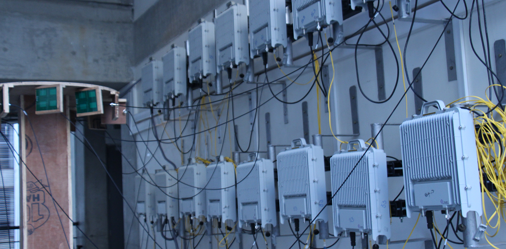
IIT Hyderabad 5G Testbed. Photo courtesy of IIT Hyderabad.
……………………………………………………………………………………………………………………………………………………………………………………………………………
TSDSI’s baseline RIT (initial description template) is documented in ITU-R WP 5D Document 5D/980: Revision 2 to Document IMT-2020/7-E, submitted on 14 February 2019. Several updates to TSDSI RIT included the updated characteristics template, initial link budget template, etc. They are in Document 5D/1138: Attachment Part 1: 5D/1138!P1; Attachment Part 2: 5D/1138!P2; Attachment Part 3: 5D/1138!P3; Attachment Part 4: 5D/1138!P4)
Here are a few key excerpts from the TSDSI baseline RIT:
Describe details of the radio interface architecture and protocol stack such as: – Logical channels – Control channels – Traffic channels Transport channels and/or physical channels.
RAN/Radio Architectures: This RIT contains NR standalone architecture. The following paragraphs provide a high-level summary of radio interface protocols and channels.
Radio Protocols: The protocol stack for the user plane includes the following: SDAP, PDCP, RLC, MAC, and PHY sublayers (terminated in UE and gNB). On the Control plane, the following protocols are defined: – RRC, PDCP, RLC, MAC and PHY sublayers (terminated in UE and gNB); – NAS protocol (terminated in UE and AMF) For details on protocol services and functions, please refer to 3GPP specifications (e.g. [38.300]).
Radio Channels (Physical, Transport and Logical Channels):
- The physical layer offers service to the MAC sublayer transport channels. The MAC sublayer offers service to the RLC sublayer logical channels.
- The RLC sublayer offers service to the PDCP sublayer RLC channels.
- The PDCP sublayer offers service to the SDAP and RRC sublayer radio bearers: data radio bearers (DRB) for user plane data and signalling radio bearers (SRB) for control plane data.
- The SDAP sublayer offers 5GC QoS flows and DRBs mapping function.
The physical channels defined in the downlink are: – the Physical Downlink Shared Channel (PDSCH), – the Physical Downlink Control Channel (PDCCH), – the Physical Broadcast Channel (PBCH).
The physical channels defined in the uplink are: – the Physical Random Access Channel (PRACH), – the Physical Uplink Shared Channel (PUSCH), – and the Physical Uplink Control Channel (PUCCH). In addition to the physical channels above, PHY layer signals are defined, which can be reference signals, primary and secondary synchronization signals.
The following transport channels, and their mapping to PHY channels, are defined:
Uplink: – Uplink Shared Channel (UL-SCH), mapped to PUSCH – Random Access Channel (RACH), mapped to PRACH
Downlink: – Downlink Shared Channel (DL-SCH), mapped to PDSCH – Broadcast channel (BCH), mapped to PBCH – Paging channel (PCH), mapped to (TBD)
Logical channels are classified into two groups: Control Channels and Traffic Channels.
Control channels: – Broadcast Control Channel (BCCH): a downlink channel for broadcasting system control information. – Paging Control Channel (PCCH): a downlink channel that transfers paging information and system information change notifications. – Common Control Channel (CCCH): channel for transmitting control information between UEs and network. – Dedicated Control Channel (DCCH): a point-to-point bi-directional channel that transmits dedicated control information between a UE and the network.
Traffic channels: Dedicated Traffic Channel (DTCH), which can exist in both UL and DL. In Downlink, the following connections between logical channels and transport channels exist: – BCCH can be mapped to BCH, or DL-SCH; – PCCH can be mapped to PCH; – CCCH, DCCH, DTCH can be mapped to DL-SCH;
In Uplink, the following connections between logical channels and transport channels exist: – CCCH, DCCH, DTCH can be mapped to UL-SCH.
Enhancements:
1. Method to improve broadcast and paging control channel efficiency over access elements.
2. Reduce the impact of congestion in the data path and control path to improve overall efficiency in the network.
3. Other aspects
– NR QoS architecture The QoS architecture in NG-RAN (connected to 5GC), can be summarized as follows: For each UE, 5GC establishes one or more PDU Sessions. For each UE, the NG-RAN establishes one or more Data Radio Bearers (DRB) per PDU Session. The NG-RAN maps packets belonging to different PDU sessions to different DRBs. Hence, the NG-RAN establishes at least one default DRB for each PDU Session. NAS level packet filters in the UE and in the 5GC associate UL and DL packets with QoS Flows. AS-level mapping rules in the UE and in the NG-RAN associate UL and DL QoS Flows with DRBs
– Carrier Aggregation (CA) In case of CA, the multi-carrier nature of the physical layer is only exposed to the MAC layer for which one HARQ entity is required per serving cell.
– Dual Connectivity (DC) In DC, the radio protocol architecture that a radio bearer uses depends on how the radio bearer is setup.
…………………………………………………………………………………………………………..
Four bearer types (information carrying channels) exist: MCG bearer, MCG split bearer, SCG bearer and SCG split bearer.
The following terminology/definitions apply:
– Master gNB: in dual connectivity, the gNB which terminates at least NG-C.
– Secondary gNB: in dual connectivity, the gNB that is providing additional radio resources for the UE but is not the Master node.
– Master Cell Group (MCG): in dual connectivity, a group of serving cells associated with the MgNB
– Secondary Cell Group (SCG): in dual connectivity, a group of serving cells associated with the SgNB
– MCG bearer: in dual connectivity, a bearer whose radio protocols are only located in the MCG.
– MCG split bearer: in dual connectivity, a bearer whose radio protocols are split at the MgNB and belong to both MCG and SCG.
– SCG bearer: in dual connectivity, a bearer whose radio protocols are only located in the SCG.
– SCG split bearer: in dual connectivity, a bearer whose radio protocols are split at the SgNB and belong to both SCG and MCG.
In case of DC, the UE is configured with two MAC entities: one MAC entity for the MCG and one MAC entity for the SCG. For a split bearer, UE is configured over which link (or both) the UE transmits UL PDCP PDUs. On the link which is not responsible for UL PDCP PDUs transmission, the RLC layer only transmits corresponding ARQ feedback for the downlink data.
What is the bit rate required for transmitting feedback information? The information will be provided in later update.
……………………………………………………………………………………………………………………
LMLC Detailed Description – Characteristics template for TSDSI RIT:
The description template provides the characteristics description of the TSDSI RIT.
For this characteristic template, it has chosen to address the characteristics that are viewed to be very crucial to assist in evaluation activities for independent evaluation groups, as well as to facilitate the understanding of the RIT.
Channel access: Describe in detail how RIT/SRIT accomplishes initial channel access, (e.g. contention or non-contention based).
Initial channel access is typically accomplished via the “random access procedure” (assuming no dedicated/scheduled resources are allocated). The random access procedure can be contention based (e.g. at initial connection from idle mode) or non-contention based (e.g. during Handover to a new cell). Random access resources and parameters are configured by the network and signaled to the UE (via broadcast or dedicated signaling). Contention based random access procedure encompasses the transmission of a random access preamble by the UE (subject to possible contention with other UEs), followed by a random access response (RAR) in DL (including allocating specific radio resources for the uplink transmission). Afterwards, the UE transmits the initial UL message (e.g. RRC connection Request) using the allocated resources, and wait for a contention resolution message in DL (to confirming access to that UE). The UE could perform multiple attempts until it is successful in accessing the channel or until a timer (supervising the procedure) elapses. Non-contention based random access procedure foresees the assignment of a dedicated random access resource/preamble to a UE (e.g. part of an HO command). This avoids the contention resolution phase, i.e. only the random access preamble and random access response messages are needed to get channel access.
From a PHY perspective, a random access preamble is transmitted (UL) in a PRACH, random access response (DL) in a PDSCH, UL transmission in a PUSCH, and contention resolution message (DL) in a PDSCH.
……………………………………………………………………………………………………………………
| Radio interface functional aspects: | ||||||||||||||||||
| Multiple access schemes
Which access scheme(s) does the proposal use? Describe in detail the multiple access schemes employed with their main parameters. – Downlink and Uplink: The multiple access is a combination of ● OFDMA: Synchronous/scheduling-based; the transmission to/from different UEs uses mutually orthogonal frequency assignments. Granularity in frequency assignment: One resource block consisting of 12 subcarriers. Multiple sub-carrier spacings are supported including 15kHz, 30kHz, 60kHz and 120kHz for data (see Item 5.2.3.2.7 and reference therein). 1. CP-OFDM is applied for downlink. DFT-spread OFDM and CP-OFDM are available for uplink. 2. Spectral confinement technique(s) (e.g. filtering, windowing, etc.) for a waveform at the transmitter is transparent to the receiver. When such confinement techniques are used, the spectral utilization ratio can be enhanced. ● TDMA: Transmission to/from different UEs with separation in time. Granularity: One slot consists of 14 OFDM symbols and the physical length of one slot ranges from 0.125ms to 1ms depending on the sub-carrier spacing (for more details on the frame structure, see Item 5.2.3.2.7 and the references therein). ● SDMA: Possibility to transmit to/from multiple users using the same time/frequency resource (SDMA a.k.a. “multi-user MIMO”) as part of the advanced-antenna capabilities (for more details on the advanced-antenna capabilities, see Item 5.2.3.2.9 and the reference therein) At least an UL transmission scheme without scheduling grant is supported for initial access. Inter-cell interference suppressed by processing gain of channel coding allowing for a frequency reuse of one (for more details on channel-coding, see Item 5.2.3.2.2.3 and the reference therein). (Note: Synchronous means that timing offset between UEs is within cyclic prefix by e.g. timing alignment.) For NB-IoT, the multiple access is a combination of OFDMA, TDMA, where OFDMA and TDMA are as follows · OFDMA: n UL: DFT-spread OFDM. Granularity in frequency domain: A single sub-carrier with either 3.75 kHz or 15 kHz sub-carrier spacing, or 3, 6, or 12 sub-carriers with a sub-carrier spacing of 15 kHz. A resource block consists of 12 sub-carriers with 15 kHz sub-carrier spacing, or 48 sub-carriers with 3.75 kHz sub-carrier spacing → 180 kHz. n DL: Granularity in frequency domain: one resource block consisting of 6 or 12 subcarriers with 15 kHz sub-carrier spacing→90 or 180 kHz · TDMA: Transmission to/from different UEs with separation in time n UL: Granularity: One resource unit of 1 ms, 2 ms, 4 ms, 8 ms, with 15 kHz sub-carrier spacing, depending on allocated number of sub-carrier(s); or 32 ms with 3.75 kHz sub-carrier spacing (for more details on the frame structure, see Item 5.2.3.2.7 and the references therein) n DL: Granularity: One resource unit (subframe) of length 1 ms. Repetition of a transmission is supported |
||||||||||||||||||
| Modulation scheme | ||||||||||||||||||
| What is the baseband modulation scheme? If both data modulation and spreading modulation are required, describe in detail.
Describe the modulation scheme employed for data and control information. What is the symbol rate after modulation? – Downlink: ● For both data and higher-layer control information: QPSK, 16QAM, 64QAM and 256QAM (see [T3.9038.211] sub-clause 7.3.1.2). ● L1/L2 control: QPSK (see [T3.9038.211] sub-clause 7.3.2.4). ● Symbol rate: 1344ksymbols/s per 1440kHz resource block (equivalently 168ksymbols/s per 180kHz resource block) – Uplink: ● For both data and higher-layer control information: π/2-BPSK with spectrum shaping, QPSK, 16QAM, 64QAM and 256QAM (see [T3.9038.211] sub-clause 6.3.1.2). ● L1/L2 control: BPSK, π/2-BPSK with spectrum shaping, QPSK (see [T3.9038.211] sub-clause 6.3.2). ● Symbol rate: 1344ksymbols/s per 1440kHz resource block (equivalently 168ksymbols/s per 180kHz resource block) The above is at least applied to eMBB. For NB-IoT, the modulation scheme is as follows. · Data and higher-layer control: π/2-BPSK (uplink only), π/4-QPSK (uplink only), QPSK · L1/L2 control: π/2-BPSK (uplink), QPSK (uplink), QPSK (downlink) Symbol rate: 168 ksymbols/s per 180 kHz resource block. For UL, less than one resource block may be allocated. |
||||||||||||||||||
| PAPR
What is the RF peak to average power ratio after baseband filtering (dB)? Describe the PAPR (peak-to-average power ratio) reduction algorithms if they are used in the proposed RIT/SRIT. The PAPR depends on the waveform and the number of component carriers. The single component carrier transmission is assumed herein when providing the PAPR. For DFT-spread OFDM, PAPR would depend on modulation scheme as well. For uplink using DFT-spread OFDM, the cubic metric (CM) can also be used as one of the methods of predicting the power de-rating from signal modulation characteristics, if needed. – Downlink: The PAPR is 8.4dB (99.9%) – Uplink: ● For CP-OFDM: The PAPR is 8.4dB (99.9%) ● For DFT-spread OFDM: The PAPR is provided in the table below.
Any PAPR-reduction algorithm is transmitter-implementation specific for uplink and downlink. For NB-IoT, – Downlink: The PAPR is 8.0dB (99.9%) on 180kHz resource. – Uplink: The PAPR is 0.23 – 5.6 dB (99.9 %) depending on sub-carriers allocated for available NB-IoT UL modulation. |
||||||||||||||||||
| Error control coding scheme and interleaving | ||||||||||||||||||
| Provide details of error control coding scheme for both downlink and uplink.
For example, – FEC or other schemes? The proponents can provide additional information on the decoding schemes. – Downlink and Uplink: ● For data: Rate 1/3 or 1/5 Low density parity check (LDPC) coding, combined with rate matching based on puncturing/repetition to achieve a desired overall code rate (For more details, see [T3.9038.212] sub-clauses 5.3.2). LDPC channel coder facilitates low-latency and high-throughput decoder implementations. ● For L1/L2 control: For DCI (Downlink Control Information)/UCI (Uplink Control Information) size larger than 11 bits, Polar coding, combined with rate matching based on puncturing/repetition to achieve a desired overall code rate (For more details, see [T3.9038.212] sub-clauses 5.3.1). Otherwise, repetition for 1-bit; simplex coding for 2-bit; reedmuller coding for 3~11-bit DCI/UCI size. The above scheme is at least applied to eMBB. Decoding mechanism is receiver-implementation specific For NB-IoT, the coding scheme is as follows: · For data: Rate 1/3 Turbo coding in UL, and rate-1/3 tail-biting convolutional coding in DL, each combined with rate matching based on puncturing/repetition to achieve a desired overall code rate; one transport block can be mapped to one or multiple resource units (for more details, see [T3.9036.212] sub-clause 6.2) · For L1/L2 control: For L1/L2 control: Rate-1/3 tail-biting convolutional coding. Special block codes for some L1/L2 control signaling (For more details, see [T3.9036.212] sub-clauses 5.1.3.1) |
||||||||||||||||||
| Describe the bit interleaving scheme for both uplink and downlink.
– Downlink: ● For data: bit interleaver is performed for LDPC coding after rate-matching (For more details, see [T3.9038.212] sub-clauses 5.4.2.2) ● For L1/L2 control: Bit interleaving is performed as part of the encoding process for Polar coding (For more details, see [T3.9038.212] sub-clauses 5.4.1.1) – Uplink: ● For data: bit interleaver is performed for LDPC coding after rate-matching (For more details, see [T3.9038.212] sub-clauses 5.4.2.2) ● For L1/L2 control: Bit interleaving is performed for Polar coding after rate-matching (For more details, see [T3.9038.212] sub-clauses 5.4.1.3) The above scheme is at least applied to eMBB. NB-IOT Uplink For Control (Format 2) : Bit interleaver is not applied For Data (Format1): Bit interleaver is performed after rate matching only for multitone transmissions (3,6,12). For single tone transmissions it is not applicable. -Downlink Bit interleaver is not applied
|
||||||||||||||||||
| Describe channel tracking capabilities (e.g. channel tracking algorithm, pilot symbol configuration, etc.) to accommodate rapidly changing delay spread profile.
To support channel tracking, different types of reference signals can be transmitted on downlink and uplink respectively. – Downlink: ● Primary and Secondary Synchronization signals (PSS and SSS) are transmitted periodically to the cell. The periodicity of these signals is network configurable. UEs can detect and maintain the cell timing based on these signals. If the gNB implements hybrid beamforming, then the PSS and SSS are transmitted separately to each analogue beam. Network can configure multiple PSS and SSS in frequency domain. ● UE-specific Demodulation RS (DM-RS) for PDCCH can be used for downlink channel estimation for coherent demodulation of PDCCH (Physical Downlink Control Channel). DM-RS for PDCCH is transmitted together with the PDCCH. ● UE-specific Demodulation RS (DM-RS) for PDSCH can be used for downlink channel estimation for coherent demodulation of PDSCH (Physical Downlink Shared Channel). DM-RS for PDSCH is transmitted together with the PDSCH. ● UE-specific Phase Tracking RS (PT-RS) can be used in addition to the DM-RS for PDSCH for correcting common phase error between PDSCH symbols not containing DM-RS. It may also be used for Doppler and time varying channel tracking. PT-RS for PDSCH is transmitted together with the PDSCH upon need. ● UE-specific Channel State Information RS (CSI-RS) can be used for estimation of channel-state information (CSI) to further prepare feedback reporting to gNB to assist in MCS selection, beamforming, MIMO rank selection and resource allocation. CSI-RS transmissions are transmitted periodically, aperiodically, and semi-persistently on a configurable rate by the gNB. CSI-RS also can be used for interference measurement and fine frequency/time tracking purposes. – Uplink: ● UE-specific Demodulation RS (DM-RS) for PUCCH can be used for uplink channel estimation for coherent demodulation of PUCCH (Physical Uplink Control Channel). DM-RS for PUCCH is transmitted together with the PUCCH. ● UE-specific Demodulation RS (DM-RS) for PUSCH can be used for uplink channel estimation for coherent demodulation of PUSCH (Physical Uplink Shared Channel). DM-RS for PUSCH is transmitted together with the PUSCH. ● UE-specific Phase Tracking RS (PT-RS) can be used in addition to the DM-RS for PUSCH for correcting common phase error between PUSCH symbols not containing DM-RS. It may also be used for Doppler and time varying channel tracking. DM-RS for PUSCH is transmitted together with the PUSCH upon need. ● UE-specific Sounding RS (SRS) can be used for estimation of uplink channel-state information to assist uplink scheduling, uplink power control, as well as assist the downlink transmission (e.g. the downlink beamforming in the scenario with UL/DL reciprocity). SRS transmissions are transmitted periodically aperiodically, and semi-persistently by the UE on a gNB configurable rate. Details of channel-tracking/estimation algorithms are receiver-implementation specific, and not part of the specification. Details of channel-tracking/estimation algorithms are receiver-implementation specific, e.g. MMSE-based channel estimation with appropriate interpolation in time and frequency domain could be used. NB-IOT NB-IoT is based on following signals transmitted in the downlink: the primary and secondary narrowband synchronization signals. The narrowband primary synchronization sequence is transmitted over 11 sub-carriers from the first subcarrier to the eleventh subcarrier in the sixth subframe of each frame, and the narrowband secondary synchronization sequence is transmitted over 12 sub-carriers in the NB-IoT carrier in the tenth subframe of every other frame. ● Demodulation RS (DM-RS) for NPUSCH format 1&2 (used for Data and control respectively) can be used for uplink channel estimation for coherent demodulation of NPUSCH F1 & F2 (Narrowband Physical Uplink Shared Channel Format 1 and 2). DM-RS for NPUSCH F1& F2 is transmitted together with the NPUSCH F1 & F2. They are not UE specific, as they do not depend on RNTI. The reference sequence generation is different for single tone and multi tone. For more details refer to [T3.9036.211] For single-tone NPUSCH with UL-SCH demodulation, uplink demodulation reference signals are transmitted in the 4- th block of the slot for 15 kHz subcarrier spacing, and in the 5-th block of the slot for 3.75 kHz subcarrier spacing. For multi-tone NPUSCH with UL-SCH demodulation, uplink demodulation reference signals are transmitted in the 4-th block of the slot. The uplink demodulation reference signals sequence length is 16 for single-tone NPUSCH with ULSCH transmission, and equals the size (number of sub-carriers) of the assigned resource for multi-tone transmission. For single-tone NPUSCH with UL-SCH transmission, multiple narrow band reference signals can be created: – Based on different base sequences; – A common Gold sequence. For multi-tone NPUSCH with UL-SCH transmission, multiple narrow band reference signals are created: – Based on different base sequences; – Different cyclic shifts of the same sequence. For NPUSCH with ACK/NAK demodulation, uplink demodulation reference signals are transmitted in the 3-rd, 4-th and 5-th block of the slot for 15 kHz subcarrier spacing, and in the 1-st, 2-nd and 3-rd block of the slot for 3.75 kHz subcarrier spacing. Multiple narrow band reference signals can be created: – Based on different base sequences; – A common Gold sequence; – Different orthogonal sequences (OCC). |
||||||||||||||||||
| Physical channel structure and multiplexing | ||||||||||||||||||
| What is the physical channel bit rate (M or Gbit/s) for supported bandwidths?
i.e., the product of the modulation symbol rate (in symbols per second), bits per modulation symbol, and the number of streams supported by the antenna system. The physical channel bit rate depends on the modulation scheme, number of spatial-multiplexing layer, number of resource blocks in the channel bandwidth and the subcarrier spacing used. The physical channel bit rate per layer can be expressed as Rlayer = Nmod x NRB x 2µ x 168 kbps where – Nmod is the number of bits per modulation symbol for the applied modulation scheme (QPSK: 2, 16QAM: 4, 64QAM: 6, 256QAM: 8) – NRB is the number of resource blocks in the aggregated frequency domain which depends on the channel bandwidth. – µ depends on the subcarrier spacing, , given by For example, a 400 MHz carrier with 264 resource blocks using 120 kHz subcarrier spacing, , and 256QAM modulation results in a physical channel bit rate of 2.8 Gbit/s per layer. NB-IOT The physical channel bit rate depends on the modulation scheme, number of tones used in the channel bandwidth in the resource block and the subcarrier spacing used. The physical channel bit rate per user can be expressed as : Uplink NPUSCH Format 1 R = Nmod x Ntone x 12 kbps for carrier spacing of 15kHz where – Nmod is the number of bits per modulation symbol for the applied modulation scheme (QPSK: 2, BPSK:1) – Ntone is the number of tones . This can be 1,3,6,12 R = Nmod x 3 kbps for carrier spacing of 3.75kHz Downlink R = Nmod x 12 x 12 kbps |
||||||||||||||||||
| Layer 1 and Layer 2 overhead estimation.
Describe how the RIT/SRIT accounts for all layer 1 (PHY) and layer 2 (MAC) overhead and provide an accurate estimate that includes static and dynamic overheads. – Downlink The downlink L1/L2 overhead includes: 1. Different types of reference signals a. Demodulation reference signals for PDSCH (DMRS-PDSCH) b. Phase-tracking reference signals for PDSCH (PTRS-PDSCH) c. Demodulation reference signals for PDCCH d. Reference signals specifically targeting estimation of channel-state information (CSI-RS) e. Tracking reference signals (TRS) 2. L1/L2 control signalling transmitted on the up to three first OFDM symbols of each slot 3. Synchronization signals and physical broadcast control channel including demodulation reference signals included in the SS/PBCH block 4. PDU headers in L2 sub-layers (MAC/RLC/PDCP) The overhead due to different type of reference signals is given in the table below. Note that demodulation reference signals for PDCCH is included in the PDCCH overhead.
The overhead due to the L1/L2 control signalling is depending on the size and periodicity of the configured CORESET in the cell and includes the overhead from the PDCCH demodulation reference signals. If the CORESET is transmitted in every slot, maximum control channel overhead is 21% assuming three symbols and whole carrier bandwidth used for CORESET, while a more typical overhead is 7% when 1/3 of the time and frequency resources in the first three symbols of a slot is allocated to PDCCH. The overhead due to the SS/PBCH block is given by the number of SS/PBCH blocks transmitted within the SS/PBCH block period, the SS/PBCH block periodicity and the subcarrier spacing. Assuming a 100 resource block wide carrier, the overhead for 20 ms periodicity is in the range of 0.6 % to 2.3 % if the maximum number of SS/PBCH blocks are transmitted. – Uplink L1/L2 overhead includes: 1. Different types of reference signals a. Demodulation reference signal for PUSCH b. Demodulation reference signal for PUCCH c. Phase-tracking reference signals a. Sounding reference signal (SRS) used for uplink channel-state estimation at the network side 2. L1/L2 control signalling transmitted on a configurable amount of resources (see also Item 4.2.3.2.4.5) 3. L2 control overhead due to e.g., random access, uplink time-alignment control, power headroom reports and buffer-status reports 4. PDU headers in L2 layers (MAC/RLC/PDCP) The overhead due to due to demodulation reference signal for PUSCH is the same as the overhead for demodulation reference signal for PDSCH, i.e. 4 % to 29 % depending on number of symbols configured. Also, the phase-tracking reference signal overhead is the same in UL as in DL. The overhead due to periodic SRS is depending on the number of symbols configured subcarrier spacing and periodicity. For 20 ms periodicity, the overhead is in the range of 0.4% to 1.4% assuming15 kHz subcarrier spacing. Amount of uplink resources reserved for random access depends on the configuration. The relative overhead due to uplink time-alignment control depends on the configuration and the number of active UEs within a cell. The amount of overhead for buffer status reports depends on the configuration. The amount of overhead caused by 4 highly depends on the data packet size. ……………………………………………………………………………………………………………….. For NB-IoT, the overhead from Narrowband RS (NRS) is dependent on the number of cell-specific antenna ports N (1 or 2) and equals 8 x N / 168 %. The overhead from NB-IoT downlink control signaling is dependent on the amount of data to be transmitted. For small infrequent data transmissions, the downlink transmissions are dominated by the L2 signaling during the connection setup. The overhead from L1 signaling is dependent on the configured scheduling cycle. The overhead due to Narrowband synchronization signal and Narrowband system information broadcast messages is only applicable to the NB-IoT anchor carrier. The actual overhead depends on the broadcasted system information messages and their periodicity. The overhead can be estimated to be around 26.25%.
For NB-IoT UL, data and control are sharing the same resources and the overhead from L1/L2 control signaling depend on the scheduled traffic in the DL. The UL control signaling is dominated by RLC and HARQ positive or negative acknowledgments. A typical NB-IoT NPRACH overhead is in the order of 5 %. |
||||||||||||||||||
| Variable bit rate capabilities:
Describe how the proposal supports different applications and services with various bit rate requirements. For a given combination of modulation scheme, code rate, and number of spatial-multiplexing layers, the data rate available to a user can be controlled by the scheduler by assigning different number of resource blocks for the transmission. In case of multiple services, the available/assigned resource, and thus the available data rate, is shared between the services. |
||||||||||||||||||
| Variable payload capabilities:
Describe how the RIT/SRIT supports IP-based application layer protocols/services (e.g., VoIP, video-streaming, interactive gaming, etc.) with variable-size payloads. See also 5.2.3.2.4.3.
The transport-block size can vary between X bits and Y bits. The number of bits per transport block can be set with a fine granularity. See [T3.9038.214] sub-clause 5.1.3.2 for details.
For NB-IoT, the maximum transport block size is 680 bits in the DL and 1000 bits in UL for the lowest UE category and 2536 bits for both DL and UL for the highest UE category. See [T3.9036.213] sub-clause 16.4.1.5.1 for details. |
||||||||||||||||||
| Signalling transmission scheme:
Describe how transmission schemes are different for signalling/control from that of user data. – Downlink L1/L2 control signalling is transmitted in assigned resources time and frequency multiplexed with data within the bandwidth part (BWP, see item 5.2.3.2.8.1). Control signalling is limited to QPSK modulation (QPSK, 16QAM, 64QAM and 256QAM for data). Control signalling error correcting codes are polar codes (LDPC codes for data). – Uplink L1/L2 control signalling transmitted in assigned resources and can be time and frequency multiplexed with data within the BWP. L1/L2 control signalling can also be multiplexed with data on the PUSCH. Modulation schemes for L1/L2 control signalling is π/2-BPSK, BPSK and QPSK. Control signalling error correcting codes are block codes for small payload and polar codes for larger payloads (LDPC codes for data).
For both downlink and uplink, higher-layer signalling (e.g. MAC, RLC, PDCP headers and RRC signalling) is carried within transport blocks and thus transmitted using the same physical-layer transmitter processing as user data.
For NB-IoT the L1/L2 control signaling is confined to a configured set of resource blocks and can be time multiplexed with data and are transmitted in scheduled subframes |
||||||||||||||||||
| Small signalling overhead
Signalling overhead refers to the radio resource that is required by the signalling divided by the total radio resource which is used to complete a transmission of a packet. The signalling includes necessary messages exchanged in DL and UL directions during a signalling mechanism, and Layer 2 protocol header for the data packet. Describe how the RIT/SRIT supports efficient mechanism to provide small signalling overhead in case of small packet transmissions. There are multiple control channel formats that have included, and provide various levels of overhead. There is an overhead versus scheduling flexibility trade-off that can be used by the scheduler to reduce the signalling overhead.
NB-IOT: In case of small data packet transmission, the L1/L2 control signalling during the connection setup procedure is dominating the uplink and downlink transmissions. To minimize this overhead NB-IoT, allows a UE to resume of an earlier connection. As an alternative, the data can be transmitted over the control plane, which eliminates the need to setup the data plane connection. |
NOTES:
1. TSDSI’s RIT is one of five proposals for the IMT 2020 RIT/SRIT.
The other four are from: 3GPP, South Korea, China, and ETSI/DECT Forum. All but the latter are based on 3GPP “5G NR.”
- The Candidate RIT/SRIT submission from China, as acknowledged in IMT-2020/5, is technically identical to the 5G NR RIT submitted from 3GPP as acknowledged in IMT-2020/3.
- The candidate RIT/SRIT submission from South Korea, as acknowledged in IMT-2020/4, is technically identical to the 5G NR RIT submitted from 3GPP as acknowledged in IMT-2020/3.
……………………………………………………………………………………………………………………………………………………………………………………………………………
2. 3GPP release 16:
As we have stated numerous times, 3GPP’s final IMT 2020 RIT/SRIT submission to ITU-R WP 5D will be largely based on 3GPP release 16 (with perhaps some elements of release 15 also included). From the 3GPP website:
Release 16 will meet the ITU IMT-2020 submission requirements and the time-plan as outlined in RP-172101.
Some Background on 3GPP Release 16:
- Early progress on Rel-16 bands for 5G
- “Working towards full 5G in Rel-16″…See a webinar presentation (Bright talk webinar)
- Preparing the ground for IMT-2020
- SA1 completes its study into 5G requirements
Here is the active status of 3GPP release 16 project.
The 3GPP release 16 completion date has been delayed by at least 3 months (1Q 2020) with no new completion date specified at this time.
3. DECT Forum/ETSI submission for IMT 2020 SRIT:
From a July 1, 2019 contribution to ITU-R WP5D Brazil meeting:
DECT Forum would like to announce its support and endorsement for the IMT-2020 contribution from ETSI for an SRIT candidate for inclusion in IMT-2020. The proposed SRIT consists of two component RITs:
⦁ DECT-2020 NR RIT
⦁ 3GPP 5G CANDIDATE FOR INCLUSION IN IMT-2020: SUBMISSION 2 FOR IMT-2020 (RIT)
DECT Forum confirms its continuation as a proponent of this IMT-2020 proposal.
……………………………………………………………………………………………………………………………………………………………………………………………………………
References:
India delays 5G trials; Advocates “the Indian Way” within ITU-R WP 5D for IMT 2020
3GPP Workshop: IMT 2020 Submission to ITU-R WP5D and Timelines for 5G Standards Completion
India’s 5G may lag due to low telecom infrastructure growth rate and insufficient fiber for backhaul
by Muntazir Abbas (edited by Alan J Weissberger) from Economic Times:
India’s 5G ambition may be thwarted as mobile infrastructure expansion is likely to remain low-paced following policy bottlenecks in the federal governance structure. Add to that India’s weak fiberization, which is mandatory for high-speed wireless network backhaul.
The country’s existing telecom infrastructure catering to a billion active subscribers may require rapid expansion, but the absence of clarity on active network sharing, distributed right-of-way norms and thin fibre penetration, may not bring 2020 a true 5G year.
The Narendra Modi-led government is eyeing to make 5G services commercially available by next year after soon-to-start field trials which would be followed by a mega spectrum sale with 275 Mhz of airwaves earmarked for the newer technology.
Plagued with high debt, the telco incumbents Vodafone Idea and Bharti Airtel, have not made much network investments over the past few years. In a constrained scenario, sharing of active and passive networks assume much significance.
The Tower and Infrastructure Providers Association (Taipa) Director General Tilak Raj Dua says, “In order to make 5G a success story in India, it is essential to invest on network densification heavily through provisioning of fiber, small cells and mobile towers.” Taipa represents telecom infrastructure companies in the country.
The India Department of Telecommunications (DoT), over the past few years, has apparently not been able to bring telecom tower companies to mainstream despite their ever-growing role in India’s digital service delivery.
The much-sought ‘infrastructure status’ accorded to the sector in 2012, has not materialised so far with firms seeking the Narendra Modi government to bring about radical reforms before the 5G make a debut.

Fiberization— A must do
Fibre-based backhaul is still in infancy in India. Industry’s assessment suggests that India’s robust 5G network would require 100 million fibre kilometres (m fkm) optic-fibre cable a year which has been growing at merely a rate of nearly 25 mfkm a year currently.
The government has recognized it as the strategic element for a high-speed data network, and has put a huge thrust and aims to increase fibre footprint to five fold or 7.5 million kilometres by 2022, from the current 1.5 million kilometers. In addition, the national policy aims to fiberise at least 60% of telecom towers by 2022, eventually accelerating migration to 5G.
“Achieving such speeds make fiber connectivity essential. India’s high population density also translates into deeper and denser fiber network,” ratings agency ICRA in its finding said, adding that the country has about 500,000 towers of which only 22% are fiberised as against 80% in China.
Earlier, telecom secretary Aruna Sundararajan said that that the department would want to benchmark how much fibre is being deployed every day to achieve 4G and 5G, and it has to become a national priority, and added that if the industry ever wants to take 5G to the villages without fibre, it would not happen, as fiberisation remains a key driver.
State-run Bharat Sanchar Nigam Limited (BSNL) that has the largest fibre base of up to 8 lakh kilometres is considering to lease out dark fibre to private players in a run up to 5G rollout that according to analysts would help operators cut Capex by leveraging state telco’s infrastructure as per need basis.
ICRA estimates the present market value of fiber assets owned by major private telecom operators stand at nearly Rs 1.25 lakh crore, with the extent of fiber rollout over the next few years would require investments of Rs 2.5 lakh crore to 3 lakh crore and sharing of fiber among multiple telcos would be the driver for a reasonable return on capital.
“5G rollout is the biggest driver for all major investment into fibre infrastructure in next five years. The next generation of technology’s performance will be dependent on the overflow of content to and from data centres,” Sandeep Aggarwal, Managing Director of Paramount Communications said, and added that the only medium capable of meeting these demands is fiber which will need to be available at every nook and corner of the country.
The government, in a recently-unveiled national policy also talked about setting up of a National Fibre Authority (NFA), but ironically there has been a dismal activity so far to take the ambitious vision forward.
The challenges, from the fibre standpoint, however, continue to remain making the 5G ride not so smooth with fibre companies together with telecom carriers seeking the Narendra Modi-led government to accelerate efforts and carve out an incentive regime.
Reliance Jio, a pure-play 4G operator that has up its ante in fibre deployment for the ambitious fibre-to-the-home (FTTH) offering dubbed as JioGigaFiber said that that to incentivise telcos, the department should draw out incentives so that operators are not challenged to deliver on fiber which is a critical element for India’s digital growth.
Earlier, Mumbai-based Jio chief Mathew Oommen said that, “service providers should use incentives for creating a deeper fiber with the redundancy of routes,” and believes that incentives should be in the form of “conducive policy to attract more investments in building fibre infrastructure” by telcos.
“5G is an interesting initiative. There is still a lag in fiber deployments in remote locations. We have learnt how to roll out fiber throughout the country, and modern technologies aligned to 5G is also one of the important factors,” R&M chairman Hans Hess told ETT.
“5G needs fiber highways and tower fiberisation is essential to be accelerated and the establishment of National Fiber Authority similar to the National Highway Authority or NHAI. These aim towards a significant portion to be invested in fibre roll out,” Sterlite Technologies Limited (STL) Group CEO Anand Agarwal told ETT.
Company’s top executive said that the national policy has accorded fibre the status of a public utility, and since fibre is essential for both wireline and wireless networks, a greater level of confidence in fibre investment was much needed.
R&M’s Hess seconded Agarwal’s views, adding that a robust fibre-based backbone would be a vital element for a network of next generation of networks.
“There would be an increase in consumption of data due to the Internet of Things (IoT) proliferation. In order to produce more data faster, a strong backbone is needed that can be built on fiber,” the Swiss company’s executive added.
“5G technology will also require a multi-fold increase in small cells deployment, with each small cell having backhaul on fibre. We are woefully inadequate in terms of optic-fibre cable density both in urban and rural areas and a special focus for its densification in a time bound manner is essential for 5G deployments,” Agarwal added.
India’s fiber coverage in kilometre per capita works out to 0.09, which is far behind 0.87 for China and more than 1.3 for the United States and Japan, according to ICRA.
The Gurugram-based firm believes that fiber density in India would have to increase at least four-fold, and that would also mean that it would evolve as a separate industry in some time, similar to the telecom tower segment in the past two decades.
Active network sharing— Do it now
The 5G, based on low latency technology, requires a dense network to seamlessly deliver Internet connectivity enabled through a telecom infrastructure such as in-building solutions, small cells, fiber and fiberised mobile towers.
In a view to ease out financially-stressed operators, the government, in the policy has envisaged active network sharing that would allow telcos to share their networks and thereby reducing their capital (Capex) as well as operational (Opex) investment. Currently, the contours of the new regime are under a discussion stage together with the department and industry, and is expected to bring much respite to 5G rollouts.
The national policy, however, talks about encouraging sharing of active infrastructure by enhancing the scope of Infrastructure Providers (IP) and promoting deployment with incentives for common sharable, passive as well as active infrastructure.
“This (active network sharing) should be done in a more structured manner. All telecom service providers should make active sharing as freely as possible that could also help them reduce Capex as well as Opex in a scenario where margins are thin,” BSNL Chairman Anupam Shrivastava said.
Shrivastava further said that it would be going to help all service providers, and added that BSNL was offering its network for sharing and the same was expected from other operators.
Sector watchdog Telecom Regulatory Authority of India (Trai), in one of its whitepaper estimates the savings on account of active infrastructure sharing to the extent of 25-35% in Opex and 33-35% in Capex.
Network sharing, according to industry analysts, can significantly bring down 5G networks rollout as well as maintenance cost. New York-based McKinsey & Company in its finding has estimated the cost reduction of up to 40% — with major savings in rollout of small cells.
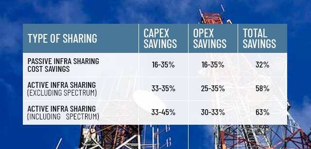
In order to have a pervasive 5G and for contiguous operations, there would have to be mushrooming of small cells over a city. Infrastructure providers can play a vital role in faster deployment of small cells that comes with a huge investment and thus support telcos to save on Capex and Opex,” he added.
Telecom carriers with 5G ambitions would be able to leverage 4G unified license (UL) coverage through dual connectivity or UL-sharing and would be able to cover larger areas with the same number of sites. 5G coverage compared to 4G coverage using 1800 MHz (megahertz) spectrum band would be about 60%.
A greenfield 5G operator, according to Taipa estimates, would need to deploy about 66% more sites to compensate for penetration losses.
Right-of-way— Not so right
The industry, demanding ease in Right-of-Way (RoW) rules, has been under continuous discussions with the regulator as well as policymakers for shaping up a comprehensive ‘dig-once’ common duct policy framework that according to the industry would help in the proliferation of 5G infrastructure across the country.
The next generation technologies are shaping the world economies and the smart cities would be built on a fibre-centric network for enabling ubiquitous and seamless connectivity. Trai is expected to come out with a policy enabling ‘common duct’ that would take telecom infrastructure to a next-level of growth.
In the last two years, post industry’s continuous rigorous follow-ups, only 13 states have to some extent aligned their policies with the Centre’s RoW rules notified in November 2016, according to Taipa.
“There is an urgent need for the states to align their telecom infrastructure policies with the Indian Telegraph Right of Way Rules to facilitate deployment of mobile infrastructure and connect the unconnected,” Dua added.
Deployment of small cells is significant for a proliferation 5G in India, the network rollout would have to be facilitated through enabling policies, which, according to the group, should include mandatory provisions for small cells at government lands and premises with new business models to excite municipal corporations and state governments.
The infrastructure providers such as Bharti Infratel, ATC Corporation and GTL Infrastructure demand a uniform RoW charges and single-window clearances nationwide to facilitate the telecom infrastructure for the digital delivery of services as envisaged by the Centre.