

Month: July 2019
ITU-R Report: U.S. Experience on the use of terrestrial IMT systems in frequency bands below 1 GHz
Draft New Report M.[IMT.EXPERIENCES] – Annex 6 U.S.A
SOURCE: U.S. via FCC
Introduction:
On March 17, 2010, the FCC released The National Broadband Plan, establishing a roadmap for initiatives to stimulate economic growth, spur job creation and boost America’s capabilities in education, health care, homeland security and more. The plan includes sections focusing on economic opportunity, education, health care, energy and the environment, government performance, civic engagement and public safety. The Plan fulfilled a Congressional mandate to ensure every American has “access to broadband capability,” including a detailed strategy for achieving affordability and maximizing use of broadband. One of the key elements of the plan is ensuring efficient allocation and use of government-owned and government-influenced assets. The Plan recommended making an additional 500 MHz of spectrum newly available for broadband within 10 years, of which 300 MHz should be available for mobile use within five years. In order to achieve this goal, the FCC established principles to:
– Enable incentives and mechanisms to repurpose spectrum to more flexible uses. Mechanisms include incentive auctions, which allow auction proceeds to be shared in an equitable manner with current licensees as market demands change. These would benefit both spectrum holders and the American public. The public could benefit from additional spectrum for high-demand uses and from new auction revenues. Incumbents, meanwhile, could recognize a portion of the value of enabling new uses of spectrum. For example, this would allow the FCC to share auction proceeds with broadcasters who voluntarily agree to use technology to continue traditional broadcast services with less spectrum.
– Ensure greater transparency of spectrum allocation, assignment and use to foster an efficient secondary market.
– Expand opportunities for innovative spectrum access models by creating new avenues for opportunistic and unlicensed use of spectrum and increasing research into new spectrum technologies.
600 MHz:
In 2014, the FCC adopted a Report and Order for Incentive Auctions. The incentive auction is a new tool authorized by Congress to help the Commission meet the Nation’s accelerating spectrum needs. Broadcasters were given the unique financial opportunity in the “reverse auction” phase of the incentive auction to return some or all of their broadcast spectrum usage rights in exchange for incentive payments. By facilitating the voluntary return of spectrum usage rights and reorganizing the broadcast television bands, the FCC could recover a portion of ultra-high frequency (“UHF”) spectrum for a “forward auction” of new, flexible-use licenses suitable for providing mobile broadband services. Payments to broadcasters that participate in the reverse auction can strengthen broadcasting by funding new content, services, and delivery mechanisms. And by making more spectrum available for mobile broadband use, the incentive auction will benefit consumers by easing congestion on the Nation’s airwaves, expediting the development of new, more robust wireless services and applications, and spurring job creation and economic growth.
The broadcast incentive auction itself comprised of two separate but interdependent auctions – a reverse auction, which will determine the price at which broadcasters will voluntarily relinquish their spectrum usage rights; and a forward auction, which will determine the price companies are willing to pay for flexible use wireless licenses. The lynchpin joining the reverse and the forward auctions is the “repacking” process. Repacking involves reorganizing and assigning channels to the remaining broadcast television stations in order to create contiguous blocks of cleared spectrum suitable for flexible use. In order to be successful, each of the components must work together. Ultimately, the reverse auction requires information about how much bidders are willing to pay for spectrum licenses in the forward auction; and the forward auction requires information regarding what spectrum rights were tendered in the reverse auction, and at what price; and each of these depend on efficiently repacking the remaining broadcasters.
The reverse and forward auctions was integrated in a series of stages. Each stage will consist of a reverse auction and a forward auction. Prior to the first stage, the initial spectrum clearing target is determined. Broadcasters indicate through the pre-auction application process their willingness to relinquish spectrum usage rights at the opening prices. Based on broadcasters’ collective willingness, the initial spectrum clearing target will be set at the highest level possible (up to 126 megahertz of spectrum) without exceeding a pre-determined national aggregate cap on the interference between wireless providers and TV stations (“impairments”) created when TV stations must be assigned to the wireless band. Under this approach, the auction system will establish a band of wireless spectrum that is generally uniform in size across all markets. Then the reverse auction bidding process will be run to determine the total amount of incentive payments to broadcasters required to clear that amount of spectrum.
The forward auction bidding process will follow the reverse auction bidding process. If the “final stage rule” is satisfied, the forward auction bidding will continue until there is no excess demand, and then the incentive auction will close. If the final stage rule is not satisfied, additional stages will be run, with progressively lower spectrum targets in the reverse auction and less spectrum available in the forward auction. The final stage rule is a set of conditions that must be met in order to close the auction at the current clearing target; failure to satisfy the rule would result in running a new phase at the next lowest clearing target.
The FCC’s central objective in designing this incentive auction is to harness the economics of demand for spectrum in order to allow market forces to determine its highest and best use. We are also mindful of the other directives that Congress established for the auction, including making all reasonable efforts to preserve, as of the date of the passage of the Spectrum Act, the coverage area and population served of remaining broadcast licensees. The auction affords a unique opportunity for broadcasters who wish to relinquish some or all of their spectrum rights, but we emphasize that a broadcaster’s decision to participate in the reverse auction is wholly voluntary. In the descending clock auction format we chose, for example, a broadcaster need only decide whether it is willing to accept one or more prices offered to it as the reverse auction proceeds; if at any point the broadcaster decides a price is too low, it may drop out of the reverse auction. No station will be compensated less than the total price that it indicates it is willing to accept.
The FCC also recognizes the importance of broadcasters that choose not to participate in the reverse auction. To free up a portion of the UHF spectrum band for new, flexible uses, Congress authorized the Commission to reorganize the broadcast television spectrum so that the stations that remain on the air after the incentive auction occupy a smaller portion of the UHF band. The reorganization (or “repacking”) approach we adopted will avoid unnecessary disruption to broadcasters and consumers and ensure the continued availability of free, over-the-air television service.
Ultimately, our actions will benefit consumers of telecommunications services. While minimizing disruption to broadcast television service, we seek to rearrange the UHF spectrum in order to increase its potential to support the changing needs of 21st Century consumers. We recognize that the same individuals may be consumers of television, mobile broadband – using both licensed and unlicensed spectrum – and other telecommunications services. To benefit such consumers, and consistent with the framework of the Spectrum Act, we have strived for balance in our decision-making process between television and wireless services, and between licensed and unlicensed spectrum uses.
Band Plan:
FCC adopted a “600 MHz Band Plan” for new services in the reorganized UHF spectrum. By maximizing the spectrum’s value to potential bidders through features such as paired five megahertz “building blocks,” the Band Plan will help to ensure a successful auction. By accommodating variation in the amount of spectrum we recover in different areas, which depends on broadcaster participation and other factors, the Band Plan will ensure that the repurposing of spectrum for the benefit of most consumers nationwide is not limited by constraints in particular markets. The Band Plan will promote competition and innovation by creating opportunities for multiple license winners and for future as well as current wireless technologies. Because it is composed of a single band of paired spectrum blocks only, our Band Plan also simplifies the forward auction design. We adopt for new licensees flexible-use service rules, and technical rules similar to those governing the adjacent 700 MHz Band, an approach that should speed deployment in the 600 MHz band. Devices will be required to be interoperable across the entire new 600 MHz Band.
The FCC concluded that the 600 MHz Band Plan we adopt best supports our central goal of allowing market forces to determine the highest and best use of spectrum, as well as our other policy goals for the incentive auction, including the Commission’s five key policy goals for selecting a band plan. The Band Plan enhances the economic value and utility of the repurposed spectrum by enabling two-way (paired) transmissions throughout this well-propagating “coverage band.” This approach also simplifies auction design by offering only a single configuration – paired blocks – which allows for maximum interchangeability of blocks, and enables limited market variation, thus avoiding a “least common denominator” problem. It also provides certainty about the operating environment for forward auction bidders by establishing guard bands between television and wireless services in order to create spectrum blocks that are reasonably designed to protect against harmful interference. Further, the 600 MHz Band Plan promotes competition. By offering only paired blocks in a single band, and by licensing on a Partial Economic Area (“PEA”) basis, the 600 MHz Band Plan will promote participation by both larger and smaller wireless providers, including rural providers, and encourage new entrants. Finally, the 600 MHz Band Plan, composed of a single, paired band, promotes interoperability and international harmonization.
The 600 MHz Band Plan we adopt consists of paired uplink and downlink bands offered in 5 + 5 megahertz blocks. The uplink band will begin at channel 51 (698 MHz), followed by a duplex gap, and then the downlink band. We will license the 600 MHz Band on a geographic area license basis, using PEAs. Further, we will accommodate market variation: specifically, we will use the 600 MHz Band Plan in all areas where sufficient spectrum is available; and in constrained markets where less spectrum is available, we may offer fewer blocks, or impaired blocks, than what we offer generally in the 600 MHz Band Plan. Finally, we establish technically reasonable guard bands to prevent harmful interference and to ensure that the spectrum blocks are as interchangeable as possible.
Because the FCC did not know the exact number of blocks licensed or their frequencies until the incentive auction concludes, the 600 MHz Band Plan we adopted represents a framework for how to license the repurposed spectrum. The Technical Appendix sets forth each of the specific 600 MHz Band Plan scenarios based on the number of television channels cleared; ultimately, the repurposed spectrum will be licensed according to one of these scenarios.
The FCC noted that offering downlink-only blocks in the 600 MHz auction may undermine competition. Because providers must pair downlink-only blocks with existing spectrum holdings, new entrants would not be able to use downlink-only blocks, thus limiting their utility. In contrast, offering paired spectrum blocks will benefit all potential 600 MHz Band licensees. Further, offering downlink-only blocks would further complicate the auction design without a commensurate benefit. As explained above, downlink-only blocks are less valuable than paired blocks to bidders, and offering both paired and unpaired blocks would introduce additional differences among licenses in the forward auction and increase the amount of time the auction takes to close.
Finally, our all-paired band plan generally has nationally consistent blocks and guard bands, which will promote interoperability. In contrast, offering downlink-only blocks could exacerbate interoperability concerns by separating the 600 MHz Band into two bands. If we license both unpaired and paired blocks, we would expect that the industry standards body would create separate bands for the paired blocks and unpaired blocks, as it has done previously. If the 600 MHz Band were split into two separate bands, then some devices could support part, but not all, of the Band. Concerns were also raised over the potential for wireless carriers using downlink-only blocks to configure their networks so as to create barriers to roaming. Limiting the auction to paired blocks will help to ameliorate these concerns. It will also promote international harmonization, and in particular, should help to address cross-border issues with Canada and Mexico.
Repurposing for Mobile Use:
On 18 January 2017, the auction satisfied both of the conditions of the final stage rule, assuring that the auction will close in Stage 4. At $19.8 billion in gross revenue for 70 MHz of spectrum, the incentive auction is among the highest grossing auctions ever conducted by the FCC. The auction created a first-of-its-kind market for repurposing commercially-held spectrum licenses for new uses. The model is part of the foundation of the future of U.S. spectrum allocation and use policy designed for 21st century realities. The US incentive auctions started in March 2016 and has satisfied the rules for the final stage which means that 84 MHz (614-698 MHz) will be cleared from broadcasting including 70 MHz of licensed spectrum and 14 MHz for unlicensed.
Frequency arrangement from US incentive auction:
Following the conclusion of the incentive auction, the transition to the reorganized UHF band will be as rapid as possible without causing unnecessary disruption. Television stations that voluntarily turn in their licenses or agree to channel share must transition from their pre-auction channels within three months of receiving their reverse auction payments. The time required for stations reassigned to a new channel to modify their facilities will vary, so we will tailor their construction deadlines to their situations. This approach will ensure that stations transition as quickly as their circumstances allow, and allow coordination of deadlines where, for example, one station must vacate a channel before another can begin operating on its new channel. No station will be allowed to operate on a channel that has been reassigned or repurposed more than 39 months after the repacking process becomes effective. In other words, the repurposed spectrum will be cleared no later than 39 months after the effective date. Most new licensees should have access to 600 MHz spectrum well before then. Consistent with Congress’s mandate, we also establish procedures to reimburse costs reasonably incurred by stations that are reassigned to new channels, as well as by multichannel video programming distributors to continue to carry such stations.
As the U.S. Congress recognized, the incentive auction and the transition that follows require coordination with our cross-border neighbors, Canada and Mexico. Because of these common borders, the Commission has established processes and agreements to protect television and wireless operations in border areas from harmful interference. The FCC staff has used these processes to fully inform Canadian and Mexican officials regarding the incentive auction and, beginning in 2013, formed technical groups to meet routinely to plan for harmonious use of the reorganized UHF band following the incentive auction. Commission leadership has supplemented these efforts, meeting with their Canadian and Mexican counterparts to emphasize the need for and mutual benefits of harmonization. We are confident that the long and successful history of close cooperation with Canada and Mexico regarding the use of radio spectrum along our common borders will continue before, during, and after the incentive auction.
700 MHz:
The recovery of the 700 MHz Band was made possible by the conversion of television broadcasting from the existing analog transmission system to a digital transmission system. Because the digital television (DTV) transmission system is more spectrally efficient than the analog system, less spectrum will be needed for broadcast television service after the transition to DTV on channels 251 is complete. The USA which switched-off its analogue transmissions in 2009, and was the first Administration to relocate the channels 52 to 69 to advanced wireless service.
The successful auction of the 700 MHz band has facilitated a nationwide roll-out of IMT (LTE) deployments, including establishing valuable spectrum for public safety uses. The U.S. 700 MHz band plan divides the 698-806 MHz frequency range into a lower 700 MHz portion and an upper 700 MHz portion. The final band plan is available at: http://wireless.fcc.gov/auctions/data/bandplans/700MHzBandPlan.pdf
To enable operability along border areas, the FCC has worked through bilateral coordination processes with its neighbours to address issues with variation in adopted band plans. The U.S. and APT FDD band plans are incompatible in their assignment of uplink and downlink spectrum therefore careful coordination of spectrum is required along the border areas. Due to overlapping base and mobile transmission of one band plan with base and mobile receiving frequencies of the other band plan, several interference scenarios can be found along the border.
According to a July 2012 survey, the U.S. 700 MHz ecosystem has grown rapidly to include 193 LTE device products including Modules for M2M, notebooks, phones, routers for hotspots, tablets and USB modems supported by over 18 manufacturers. 3GPP defines a number of bands in 700 MHz: Band 12: (Lower 700 MHz) 699 MHz-716 MHz /729 MHz-746 MHz; Band 13: (Upper C 700 MHz) 777 MHz-787 MHz /746 MHz-756 MHz; Band 14: (Upper D 700 MHz) 788 MHz798 MHz /758 MHz-768 MHz; Band 17: (Lower B, C 700 MHz) 704 MHz-716 MHz /734 MHz-746 MHz.
OpenSignal: U.S. has fastest “5G” download speed out of 8 countries tested
by Ian Fogg, OpenSignal (edited and augmented by Alan J Weissberger)
Overview:
In Opensignal’s latest analysis of 5G, we’ve looked at the maximum real-world speeds seen in eight countries which have launched 5G services. The maximum download speeds smartphone users see are much faster than the average speeds experienced by 5G users as the market research firm expected. OpenSignal relies on crowd-sourced, device-based data and regular application servers for its information on user-experienced speeds, as opposed to test servers that may be located within an operator’s network. Data was collected between April 1st and June 30th.
The highest maximum speeds were seen by 5G users in the U.S. with 1815 Mbps, which is approximately three times as fast as 4G users’ maximum speed. Switzerland followed in second place with 1145 Mbps and South Korea ranked third with 5G users’ maximum speed of 1071 Mbps. The speeds we measured in these three leading countries were significantly faster than the maximum speed in European markets where 5G has only just launched such as Italy or Spain, or in the UK where the first operator to launch 5G only has 40 MHz of suitable spectrum which is far below 5G technology’s 100 MHz channel size sweet spot.
The current 5G maximum speed is so much greater in the U.S., because wireless network operators there are already able to use mmWave spectrum for 5G. This is extremely high capacity and extremely fast spectrum but has very limited coverage compared with the 3.4-3.8 GHz 5G “mid band” spectrum typically used in most of the other countries we analyzed where mmWave spectrum is not yet available.
Real-world measurements of 5G maximum speed accurately record the experience:
Opensignal says they focus on analyzing the true end-to-end network experience of mobile users. Our approach means the speeds we measure represent the typical real-world experience of smartphone users. This means other speed tests which use dedicated test servers that are often located very close to a user inside the same operator’s network will inflate speeds compared with Opensignal’s real-world measurement of maximum speed.
To measure the real-world experience accurately, Opensignal’s tests connect our users’ smartphones to the same servers that host all the popular mobile apps and websites which all smartphone users connect to daily.
Editor’s Note: Some deployed pre-standard 5G networks (like AT&T’s) don’t have 5G smartphone endpoints at this time. AT&T only sells a Netgear “puck” which is a WiFi router with AT&T’s 5G used for backhaul.
…………………………………………………………………………………………………………………………………………………………………………………………..

……………………………………………………………………………………………………………………………
The 5G experience is set to improve quickly:
At this early stage of the 5G era, the maximum speeds are already many times higher than the maximum speed we have measured with our 4G users. The difference between 5G users’ max speed and 4G users ranged from 2.7 times as fast in the USA, 2.6 times as fast in Switzerland, down to Australia where the maximum speed experienced by 4G users was so extremely fast – close to the theoretical best performance of 4G – that the maximum 5G speed was actually slightly slower than the maximum 4G speed.
Opensignal expects 5G maximum speeds to continue to increase as 5G expands its reach. This is just the start of the 5G era and the market is moving quickly. More 5G services will launch using more spectrum and wider channels — there are few 5G services currently using 5G’s ideal 100 MHz channel size — and 5G technology evolves to be able to combine the performance of multiple 5G channels and bands together to boost both the maximum and average 5G speeds and further improve the mobile user experience of 5G users.
It’s quite interesting that OpenSignal’s analysis found that 4G LTE users in Australia actually have peak speeds faster than 5G speeds: 950 Mbps on 4G versus 792 Mbps on 5G. OpenSignal noted that Australia’s 4G performance is close to the theoretical limits of 4G LTE.
References:
Telecom Italia to deploy “5G” in 6 More Italian Cities by 2019 year-end
Telecom Italia (TIM) has already deployed pre-standard “5G” in Rome and Turin and recently added Naples. TIM will further extend 5G service to another six Italian cities, including Milan, Bologna, Verona, Florence, Matera, and Bari. That will also include 30 tourist destinations, 50 industrial districts, and 30 specific projects for big businesses, with speeds of up to 2G b/sec.
TIM is in partnership with Samsung, Xiaomi and Oppo to enable an immediate use of the new 5G network. TIM will also offer the 5G roaming services in six countries, starting within July in Austria, Great Britain and Switzerland and moving on to Spain, Germany and the UAE.
Telecom Italia plans to cover 120 Italian cities within two years, or 22% of the population, it said in a statement. The largest Italian telco is also negotiating with rival Vodafone to share 5G infrastructure to deliver services at a lower cost across wider areas of the country.
TIM will offer tiered data-download packages to consumers and business clients, rather than unlimited data plans, according to details of its offers outlined on Friday July 5th. Consumers, as well as business customers, can visit the company website at www.tim.it to buy a handset of their choice with selective subscription plans.

Telecom Italia’s new logo. Photo courtesy of Reuters
………………………………………………………………………………………………
In 2017, Turin became the first Italian city with a 5G mobile network after the municipality signed a memorandum of understanding (MoU) with the company, which announced at that time that it would install more than 100 small cells in the main areas of the city. It had proclaimed that the project would start its metropolitan trial in 2018, with the aim of covering the whole city by 2020.
Later that year, another 5G MoU was signed by the company with San Marino. The republic, which has a population of 33,000 and an area of 61.2 square kilometres, started working with TIM to update its mobile sites with 4G+ (LTE Advanced Pro) and introduce features such as MIMO 4×4, carrier aggregation, superior modulation, and cloud architecture.
TIM was the first operator to activate a 5G millimetre-wave antenna in Italy, the first to offer complete 5G coverage for the Republic of San Marino and the first in Italy to demonstrate a car being driven remotely through 5G, together with Ericsson – with whom the current creation of the commercial network has begun – and the Municipality of Turin. As part of the Bari-Matera experiment undertaken in agreement with the MiSE, around 70 5G use cases have been defined and many of these have already been implemented or are being finalised. Thanks to TIM 5G, this year’s Giro d’Italia fans could follow the Riccione–San Marino stage in real time with 360° cameras and enjoy a genuinely immersive entertainment experience.
References:
https://www.lightreading.com/mobile/5g/tim-launches-5g-services/d/d-id/752588
……………………………………………………………………………………….
The Long Rollout for 5G (from June 29th Wall Street Journal):
Some analysts and industry insiders think even a decade isn’t long enough, warning that a lack of cash and local cooperation could slow 5G rollout or even stall it completely outside the richest, densest cities.
India’s TSDSI candidate IMT 2020 RIT with Low Mobility Large Cell (LMLC) for rural coverage of 5G services
India’s telecom standards organization TSDSI has submitted its candidate IMT-2020 Radio Interface Technology (RIT) to the IMT-2020 evaluation at the ITU-R WP 5D meeting #32 being held in Buzios, Brazil from 9 July 2019 to 17 July 2019. TSDSI’s IMT 2020 submission is one of five candidate RIT proposals- see NOTE at bottom of this article for more information.
TSDSI’s RIT is described in document ITU-R WP5D-AR Contribution 770. This RIT has been developed to address the rural requirements by enabling the implementation of Low Mobility Large Cell (LMLC), particularly with emphasis on low-cost rural coverage of 5G wireless network services. TSDSI believes that this RIT will also help to meet the rural requirements of other developing countries. This author agrees!
TSDSI proposal on Low Mobility Large Cell (LMLC) configuration has been included as a mandatory test configuration under the Rural eMBB (enhanced Mobile BroadBand) test environment in IMT 2020 Technical Performance Requirements (TPR) in ITU-R with an enhanced Inter Sire Distance (ISD) of 6 km. Incorporation of LMLC in IMT2020 will help address the requirements of typical Indian rural settings and will be a key enabler for bridging the rural-urban divide with 5G rollouts.
–>The Indian administration (ITU member country) extends its support to the RIT of TSDSI and solicits the support of ITU Member States to support this proposal.
Indian wireless network operators, including Reliance Jio Infocomm Ltd, have expressed interest in LMLC.
About TSDSI:
*TSDSI is a Standards development organization similar to ETSI, SRIB, ATIS, CCSA, TTA, TTC, etc.
*TSDSI is an Organisational Partner of 3GPP and oneM2M, an Associate member of ITU-R and ITU-T and a member of GSC.
*TSDSI delegations have been actively participating and contributing in Standards development Working Groups in all these forums.
*TSDSI has formal affiliations (MoUs/Agreements) with – ETSI, 5GIA, ATSC, BIF, CCICI, GCF, IEEE-SA, TIA, TAICs, TTA, WWRF, ARIB, ATIS, CCSA, TTC
*TSDSI conducts several joint activities – projects, workshops, conferences etc. with its affiliates
*TSDSI’s operating procedures have been derived based on best practices being followed by similar Global SDOs.
*TSDSI Rules & Regulations, Working Procedures and IPR Policy are all transparent and available on our website – http://www.tsdsi.in. A brief perusal will show the similarity with the processes and policies followed by other SDOs.
*TSDSI strictly follows the Rules and Procedures. It provides an open, transparent and collaborative platform for its members to participate and contribute in the development of Standards with a special focus on India Specific Requirements and Indian Innovations. The governance model is also very inclusive, open and transparent with fresh elections being conducted for all positions every 2 years.
Submitted by: Chair TSDSI , Vice Chair TSDSI and DG TSDSI
http://www.tsdsi.in
………………………………………………………………………………………………………………………………………….
Kiran Kumar Kuchi, a professor at IIT Hyderabad is building a 5G testbed there. The system will exceed IMT 2020 5G performance requirements including Low Mobility Large Cell.
IIT Hyderabad 5G Testbed. Photo courtesy of IIT Hyderabad.
……………………………………………………………………………………………………………………………………………………………………………………………………………
TSDSI’s baseline RIT (initial description template) is documented in ITU-R WP 5D Document 5D/980: Revision 2 to Document IMT-2020/7-E, submitted on 14 February 2019. Several updates to TSDSI RIT included the updated characteristics template, initial link budget template, etc. They are in Document 5D/1138: Attachment Part 1: 5D/1138!P1; Attachment Part 2: 5D/1138!P2; Attachment Part 3: 5D/1138!P3; Attachment Part 4: 5D/1138!P4)
Here are a few key excerpts from the TSDSI baseline RIT:
Describe details of the radio interface architecture and protocol stack such as: – Logical channels – Control channels – Traffic channels Transport channels and/or physical channels.
RAN/Radio Architectures: This RIT contains NR standalone architecture. The following paragraphs provide a high-level summary of radio interface protocols and channels.
Radio Protocols: The protocol stack for the user plane includes the following: SDAP, PDCP, RLC, MAC, and PHY sublayers (terminated in UE and gNB). On the Control plane, the following protocols are defined: – RRC, PDCP, RLC, MAC and PHY sublayers (terminated in UE and gNB); – NAS protocol (terminated in UE and AMF) For details on protocol services and functions, please refer to 3GPP specifications (e.g. [38.300]).
Radio Channels (Physical, Transport and Logical Channels):
- The physical layer offers service to the MAC sublayer transport channels. The MAC sublayer offers service to the RLC sublayer logical channels.
- The RLC sublayer offers service to the PDCP sublayer RLC channels.
- The PDCP sublayer offers service to the SDAP and RRC sublayer radio bearers: data radio bearers (DRB) for user plane data and signalling radio bearers (SRB) for control plane data.
- The SDAP sublayer offers 5GC QoS flows and DRBs mapping function.
The physical channels defined in the downlink are: – the Physical Downlink Shared Channel (PDSCH), – the Physical Downlink Control Channel (PDCCH), – the Physical Broadcast Channel (PBCH).
The physical channels defined in the uplink are: – the Physical Random Access Channel (PRACH), – the Physical Uplink Shared Channel (PUSCH), – and the Physical Uplink Control Channel (PUCCH). In addition to the physical channels above, PHY layer signals are defined, which can be reference signals, primary and secondary synchronization signals.
The following transport channels, and their mapping to PHY channels, are defined:
Uplink: – Uplink Shared Channel (UL-SCH), mapped to PUSCH – Random Access Channel (RACH), mapped to PRACH
Downlink: – Downlink Shared Channel (DL-SCH), mapped to PDSCH – Broadcast channel (BCH), mapped to PBCH – Paging channel (PCH), mapped to (TBD)
Logical channels are classified into two groups: Control Channels and Traffic Channels.
Control channels: – Broadcast Control Channel (BCCH): a downlink channel for broadcasting system control information. – Paging Control Channel (PCCH): a downlink channel that transfers paging information and system information change notifications. – Common Control Channel (CCCH): channel for transmitting control information between UEs and network. – Dedicated Control Channel (DCCH): a point-to-point bi-directional channel that transmits dedicated control information between a UE and the network.
Traffic channels: Dedicated Traffic Channel (DTCH), which can exist in both UL and DL. In Downlink, the following connections between logical channels and transport channels exist: – BCCH can be mapped to BCH, or DL-SCH; – PCCH can be mapped to PCH; – CCCH, DCCH, DTCH can be mapped to DL-SCH;
In Uplink, the following connections between logical channels and transport channels exist: – CCCH, DCCH, DTCH can be mapped to UL-SCH.
Enhancements:
1. Method to improve broadcast and paging control channel efficiency over access elements.
2. Reduce the impact of congestion in the data path and control path to improve overall efficiency in the network.
3. Other aspects
– NR QoS architecture The QoS architecture in NG-RAN (connected to 5GC), can be summarized as follows: For each UE, 5GC establishes one or more PDU Sessions. For each UE, the NG-RAN establishes one or more Data Radio Bearers (DRB) per PDU Session. The NG-RAN maps packets belonging to different PDU sessions to different DRBs. Hence, the NG-RAN establishes at least one default DRB for each PDU Session. NAS level packet filters in the UE and in the 5GC associate UL and DL packets with QoS Flows. AS-level mapping rules in the UE and in the NG-RAN associate UL and DL QoS Flows with DRBs
– Carrier Aggregation (CA) In case of CA, the multi-carrier nature of the physical layer is only exposed to the MAC layer for which one HARQ entity is required per serving cell.
– Dual Connectivity (DC) In DC, the radio protocol architecture that a radio bearer uses depends on how the radio bearer is setup.
…………………………………………………………………………………………………………..
Four bearer types (information carrying channels) exist: MCG bearer, MCG split bearer, SCG bearer and SCG split bearer.
The following terminology/definitions apply:
– Master gNB: in dual connectivity, the gNB which terminates at least NG-C.
– Secondary gNB: in dual connectivity, the gNB that is providing additional radio resources for the UE but is not the Master node.
– Master Cell Group (MCG): in dual connectivity, a group of serving cells associated with the MgNB
– Secondary Cell Group (SCG): in dual connectivity, a group of serving cells associated with the SgNB
– MCG bearer: in dual connectivity, a bearer whose radio protocols are only located in the MCG.
– MCG split bearer: in dual connectivity, a bearer whose radio protocols are split at the MgNB and belong to both MCG and SCG.
– SCG bearer: in dual connectivity, a bearer whose radio protocols are only located in the SCG.
– SCG split bearer: in dual connectivity, a bearer whose radio protocols are split at the SgNB and belong to both SCG and MCG.
In case of DC, the UE is configured with two MAC entities: one MAC entity for the MCG and one MAC entity for the SCG. For a split bearer, UE is configured over which link (or both) the UE transmits UL PDCP PDUs. On the link which is not responsible for UL PDCP PDUs transmission, the RLC layer only transmits corresponding ARQ feedback for the downlink data.
What is the bit rate required for transmitting feedback information? The information will be provided in later update.
……………………………………………………………………………………………………………………
LMLC Detailed Description – Characteristics template for TSDSI RIT:
The description template provides the characteristics description of the TSDSI RIT.
For this characteristic template, it has chosen to address the characteristics that are viewed to be very crucial to assist in evaluation activities for independent evaluation groups, as well as to facilitate the understanding of the RIT.
Channel access: Describe in detail how RIT/SRIT accomplishes initial channel access, (e.g. contention or non-contention based).
Initial channel access is typically accomplished via the “random access procedure” (assuming no dedicated/scheduled resources are allocated). The random access procedure can be contention based (e.g. at initial connection from idle mode) or non-contention based (e.g. during Handover to a new cell). Random access resources and parameters are configured by the network and signaled to the UE (via broadcast or dedicated signaling). Contention based random access procedure encompasses the transmission of a random access preamble by the UE (subject to possible contention with other UEs), followed by a random access response (RAR) in DL (including allocating specific radio resources for the uplink transmission). Afterwards, the UE transmits the initial UL message (e.g. RRC connection Request) using the allocated resources, and wait for a contention resolution message in DL (to confirming access to that UE). The UE could perform multiple attempts until it is successful in accessing the channel or until a timer (supervising the procedure) elapses. Non-contention based random access procedure foresees the assignment of a dedicated random access resource/preamble to a UE (e.g. part of an HO command). This avoids the contention resolution phase, i.e. only the random access preamble and random access response messages are needed to get channel access.
From a PHY perspective, a random access preamble is transmitted (UL) in a PRACH, random access response (DL) in a PDSCH, UL transmission in a PUSCH, and contention resolution message (DL) in a PDSCH.
……………………………………………………………………………………………………………………
| Radio interface functional aspects: | ||||||||||||||||||
| Multiple access schemes
Which access scheme(s) does the proposal use? Describe in detail the multiple access schemes employed with their main parameters. – Downlink and Uplink: The multiple access is a combination of ● OFDMA: Synchronous/scheduling-based; the transmission to/from different UEs uses mutually orthogonal frequency assignments. Granularity in frequency assignment: One resource block consisting of 12 subcarriers. Multiple sub-carrier spacings are supported including 15kHz, 30kHz, 60kHz and 120kHz for data (see Item 5.2.3.2.7 and reference therein). 1. CP-OFDM is applied for downlink. DFT-spread OFDM and CP-OFDM are available for uplink. 2. Spectral confinement technique(s) (e.g. filtering, windowing, etc.) for a waveform at the transmitter is transparent to the receiver. When such confinement techniques are used, the spectral utilization ratio can be enhanced. ● TDMA: Transmission to/from different UEs with separation in time. Granularity: One slot consists of 14 OFDM symbols and the physical length of one slot ranges from 0.125ms to 1ms depending on the sub-carrier spacing (for more details on the frame structure, see Item 5.2.3.2.7 and the references therein). ● SDMA: Possibility to transmit to/from multiple users using the same time/frequency resource (SDMA a.k.a. “multi-user MIMO”) as part of the advanced-antenna capabilities (for more details on the advanced-antenna capabilities, see Item 5.2.3.2.9 and the reference therein) At least an UL transmission scheme without scheduling grant is supported for initial access. Inter-cell interference suppressed by processing gain of channel coding allowing for a frequency reuse of one (for more details on channel-coding, see Item 5.2.3.2.2.3 and the reference therein). (Note: Synchronous means that timing offset between UEs is within cyclic prefix by e.g. timing alignment.) For NB-IoT, the multiple access is a combination of OFDMA, TDMA, where OFDMA and TDMA are as follows · OFDMA: n UL: DFT-spread OFDM. Granularity in frequency domain: A single sub-carrier with either 3.75 kHz or 15 kHz sub-carrier spacing, or 3, 6, or 12 sub-carriers with a sub-carrier spacing of 15 kHz. A resource block consists of 12 sub-carriers with 15 kHz sub-carrier spacing, or 48 sub-carriers with 3.75 kHz sub-carrier spacing → 180 kHz. n DL: Granularity in frequency domain: one resource block consisting of 6 or 12 subcarriers with 15 kHz sub-carrier spacing→90 or 180 kHz · TDMA: Transmission to/from different UEs with separation in time n UL: Granularity: One resource unit of 1 ms, 2 ms, 4 ms, 8 ms, with 15 kHz sub-carrier spacing, depending on allocated number of sub-carrier(s); or 32 ms with 3.75 kHz sub-carrier spacing (for more details on the frame structure, see Item 5.2.3.2.7 and the references therein) n DL: Granularity: One resource unit (subframe) of length 1 ms. Repetition of a transmission is supported |
||||||||||||||||||
| Modulation scheme | ||||||||||||||||||
| What is the baseband modulation scheme? If both data modulation and spreading modulation are required, describe in detail.
Describe the modulation scheme employed for data and control information. What is the symbol rate after modulation? – Downlink: ● For both data and higher-layer control information: QPSK, 16QAM, 64QAM and 256QAM (see [T3.9038.211] sub-clause 7.3.1.2). ● L1/L2 control: QPSK (see [T3.9038.211] sub-clause 7.3.2.4). ● Symbol rate: 1344ksymbols/s per 1440kHz resource block (equivalently 168ksymbols/s per 180kHz resource block) – Uplink: ● For both data and higher-layer control information: π/2-BPSK with spectrum shaping, QPSK, 16QAM, 64QAM and 256QAM (see [T3.9038.211] sub-clause 6.3.1.2). ● L1/L2 control: BPSK, π/2-BPSK with spectrum shaping, QPSK (see [T3.9038.211] sub-clause 6.3.2). ● Symbol rate: 1344ksymbols/s per 1440kHz resource block (equivalently 168ksymbols/s per 180kHz resource block) The above is at least applied to eMBB. For NB-IoT, the modulation scheme is as follows. · Data and higher-layer control: π/2-BPSK (uplink only), π/4-QPSK (uplink only), QPSK · L1/L2 control: π/2-BPSK (uplink), QPSK (uplink), QPSK (downlink) Symbol rate: 168 ksymbols/s per 180 kHz resource block. For UL, less than one resource block may be allocated. |
||||||||||||||||||
| PAPR
What is the RF peak to average power ratio after baseband filtering (dB)? Describe the PAPR (peak-to-average power ratio) reduction algorithms if they are used in the proposed RIT/SRIT. The PAPR depends on the waveform and the number of component carriers. The single component carrier transmission is assumed herein when providing the PAPR. For DFT-spread OFDM, PAPR would depend on modulation scheme as well. For uplink using DFT-spread OFDM, the cubic metric (CM) can also be used as one of the methods of predicting the power de-rating from signal modulation characteristics, if needed. – Downlink: The PAPR is 8.4dB (99.9%) – Uplink: ● For CP-OFDM: The PAPR is 8.4dB (99.9%) ● For DFT-spread OFDM: The PAPR is provided in the table below.
Any PAPR-reduction algorithm is transmitter-implementation specific for uplink and downlink. For NB-IoT, – Downlink: The PAPR is 8.0dB (99.9%) on 180kHz resource. – Uplink: The PAPR is 0.23 – 5.6 dB (99.9 %) depending on sub-carriers allocated for available NB-IoT UL modulation. |
||||||||||||||||||
| Error control coding scheme and interleaving | ||||||||||||||||||
| Provide details of error control coding scheme for both downlink and uplink.
For example, – FEC or other schemes? The proponents can provide additional information on the decoding schemes. – Downlink and Uplink: ● For data: Rate 1/3 or 1/5 Low density parity check (LDPC) coding, combined with rate matching based on puncturing/repetition to achieve a desired overall code rate (For more details, see [T3.9038.212] sub-clauses 5.3.2). LDPC channel coder facilitates low-latency and high-throughput decoder implementations. ● For L1/L2 control: For DCI (Downlink Control Information)/UCI (Uplink Control Information) size larger than 11 bits, Polar coding, combined with rate matching based on puncturing/repetition to achieve a desired overall code rate (For more details, see [T3.9038.212] sub-clauses 5.3.1). Otherwise, repetition for 1-bit; simplex coding for 2-bit; reedmuller coding for 3~11-bit DCI/UCI size. The above scheme is at least applied to eMBB. Decoding mechanism is receiver-implementation specific For NB-IoT, the coding scheme is as follows: · For data: Rate 1/3 Turbo coding in UL, and rate-1/3 tail-biting convolutional coding in DL, each combined with rate matching based on puncturing/repetition to achieve a desired overall code rate; one transport block can be mapped to one or multiple resource units (for more details, see [T3.9036.212] sub-clause 6.2) · For L1/L2 control: For L1/L2 control: Rate-1/3 tail-biting convolutional coding. Special block codes for some L1/L2 control signaling (For more details, see [T3.9036.212] sub-clauses 5.1.3.1) |
||||||||||||||||||
| Describe the bit interleaving scheme for both uplink and downlink.
– Downlink: ● For data: bit interleaver is performed for LDPC coding after rate-matching (For more details, see [T3.9038.212] sub-clauses 5.4.2.2) ● For L1/L2 control: Bit interleaving is performed as part of the encoding process for Polar coding (For more details, see [T3.9038.212] sub-clauses 5.4.1.1) – Uplink: ● For data: bit interleaver is performed for LDPC coding after rate-matching (For more details, see [T3.9038.212] sub-clauses 5.4.2.2) ● For L1/L2 control: Bit interleaving is performed for Polar coding after rate-matching (For more details, see [T3.9038.212] sub-clauses 5.4.1.3) The above scheme is at least applied to eMBB. NB-IOT Uplink For Control (Format 2) : Bit interleaver is not applied For Data (Format1): Bit interleaver is performed after rate matching only for multitone transmissions (3,6,12). For single tone transmissions it is not applicable. -Downlink Bit interleaver is not applied
|
||||||||||||||||||
| Describe channel tracking capabilities (e.g. channel tracking algorithm, pilot symbol configuration, etc.) to accommodate rapidly changing delay spread profile.
To support channel tracking, different types of reference signals can be transmitted on downlink and uplink respectively. – Downlink: ● Primary and Secondary Synchronization signals (PSS and SSS) are transmitted periodically to the cell. The periodicity of these signals is network configurable. UEs can detect and maintain the cell timing based on these signals. If the gNB implements hybrid beamforming, then the PSS and SSS are transmitted separately to each analogue beam. Network can configure multiple PSS and SSS in frequency domain. ● UE-specific Demodulation RS (DM-RS) for PDCCH can be used for downlink channel estimation for coherent demodulation of PDCCH (Physical Downlink Control Channel). DM-RS for PDCCH is transmitted together with the PDCCH. ● UE-specific Demodulation RS (DM-RS) for PDSCH can be used for downlink channel estimation for coherent demodulation of PDSCH (Physical Downlink Shared Channel). DM-RS for PDSCH is transmitted together with the PDSCH. ● UE-specific Phase Tracking RS (PT-RS) can be used in addition to the DM-RS for PDSCH for correcting common phase error between PDSCH symbols not containing DM-RS. It may also be used for Doppler and time varying channel tracking. PT-RS for PDSCH is transmitted together with the PDSCH upon need. ● UE-specific Channel State Information RS (CSI-RS) can be used for estimation of channel-state information (CSI) to further prepare feedback reporting to gNB to assist in MCS selection, beamforming, MIMO rank selection and resource allocation. CSI-RS transmissions are transmitted periodically, aperiodically, and semi-persistently on a configurable rate by the gNB. CSI-RS also can be used for interference measurement and fine frequency/time tracking purposes. – Uplink: ● UE-specific Demodulation RS (DM-RS) for PUCCH can be used for uplink channel estimation for coherent demodulation of PUCCH (Physical Uplink Control Channel). DM-RS for PUCCH is transmitted together with the PUCCH. ● UE-specific Demodulation RS (DM-RS) for PUSCH can be used for uplink channel estimation for coherent demodulation of PUSCH (Physical Uplink Shared Channel). DM-RS for PUSCH is transmitted together with the PUSCH. ● UE-specific Phase Tracking RS (PT-RS) can be used in addition to the DM-RS for PUSCH for correcting common phase error between PUSCH symbols not containing DM-RS. It may also be used for Doppler and time varying channel tracking. DM-RS for PUSCH is transmitted together with the PUSCH upon need. ● UE-specific Sounding RS (SRS) can be used for estimation of uplink channel-state information to assist uplink scheduling, uplink power control, as well as assist the downlink transmission (e.g. the downlink beamforming in the scenario with UL/DL reciprocity). SRS transmissions are transmitted periodically aperiodically, and semi-persistently by the UE on a gNB configurable rate. Details of channel-tracking/estimation algorithms are receiver-implementation specific, and not part of the specification. Details of channel-tracking/estimation algorithms are receiver-implementation specific, e.g. MMSE-based channel estimation with appropriate interpolation in time and frequency domain could be used. NB-IOT NB-IoT is based on following signals transmitted in the downlink: the primary and secondary narrowband synchronization signals. The narrowband primary synchronization sequence is transmitted over 11 sub-carriers from the first subcarrier to the eleventh subcarrier in the sixth subframe of each frame, and the narrowband secondary synchronization sequence is transmitted over 12 sub-carriers in the NB-IoT carrier in the tenth subframe of every other frame. ● Demodulation RS (DM-RS) for NPUSCH format 1&2 (used for Data and control respectively) can be used for uplink channel estimation for coherent demodulation of NPUSCH F1 & F2 (Narrowband Physical Uplink Shared Channel Format 1 and 2). DM-RS for NPUSCH F1& F2 is transmitted together with the NPUSCH F1 & F2. They are not UE specific, as they do not depend on RNTI. The reference sequence generation is different for single tone and multi tone. For more details refer to [T3.9036.211] For single-tone NPUSCH with UL-SCH demodulation, uplink demodulation reference signals are transmitted in the 4- th block of the slot for 15 kHz subcarrier spacing, and in the 5-th block of the slot for 3.75 kHz subcarrier spacing. For multi-tone NPUSCH with UL-SCH demodulation, uplink demodulation reference signals are transmitted in the 4-th block of the slot. The uplink demodulation reference signals sequence length is 16 for single-tone NPUSCH with ULSCH transmission, and equals the size (number of sub-carriers) of the assigned resource for multi-tone transmission. For single-tone NPUSCH with UL-SCH transmission, multiple narrow band reference signals can be created: – Based on different base sequences; – A common Gold sequence. For multi-tone NPUSCH with UL-SCH transmission, multiple narrow band reference signals are created: – Based on different base sequences; – Different cyclic shifts of the same sequence. For NPUSCH with ACK/NAK demodulation, uplink demodulation reference signals are transmitted in the 3-rd, 4-th and 5-th block of the slot for 15 kHz subcarrier spacing, and in the 1-st, 2-nd and 3-rd block of the slot for 3.75 kHz subcarrier spacing. Multiple narrow band reference signals can be created: – Based on different base sequences; – A common Gold sequence; – Different orthogonal sequences (OCC). |
||||||||||||||||||
| Physical channel structure and multiplexing | ||||||||||||||||||
| What is the physical channel bit rate (M or Gbit/s) for supported bandwidths?
i.e., the product of the modulation symbol rate (in symbols per second), bits per modulation symbol, and the number of streams supported by the antenna system. The physical channel bit rate depends on the modulation scheme, number of spatial-multiplexing layer, number of resource blocks in the channel bandwidth and the subcarrier spacing used. The physical channel bit rate per layer can be expressed as Rlayer = Nmod x NRB x 2µ x 168 kbps where – Nmod is the number of bits per modulation symbol for the applied modulation scheme (QPSK: 2, 16QAM: 4, 64QAM: 6, 256QAM: 8) – NRB is the number of resource blocks in the aggregated frequency domain which depends on the channel bandwidth. – µ depends on the subcarrier spacing, , given by For example, a 400 MHz carrier with 264 resource blocks using 120 kHz subcarrier spacing, , and 256QAM modulation results in a physical channel bit rate of 2.8 Gbit/s per layer. NB-IOT The physical channel bit rate depends on the modulation scheme, number of tones used in the channel bandwidth in the resource block and the subcarrier spacing used. The physical channel bit rate per user can be expressed as : Uplink NPUSCH Format 1 R = Nmod x Ntone x 12 kbps for carrier spacing of 15kHz where – Nmod is the number of bits per modulation symbol for the applied modulation scheme (QPSK: 2, BPSK:1) – Ntone is the number of tones . This can be 1,3,6,12 R = Nmod x 3 kbps for carrier spacing of 3.75kHz Downlink R = Nmod x 12 x 12 kbps |
||||||||||||||||||
| Layer 1 and Layer 2 overhead estimation.
Describe how the RIT/SRIT accounts for all layer 1 (PHY) and layer 2 (MAC) overhead and provide an accurate estimate that includes static and dynamic overheads. – Downlink The downlink L1/L2 overhead includes: 1. Different types of reference signals a. Demodulation reference signals for PDSCH (DMRS-PDSCH) b. Phase-tracking reference signals for PDSCH (PTRS-PDSCH) c. Demodulation reference signals for PDCCH d. Reference signals specifically targeting estimation of channel-state information (CSI-RS) e. Tracking reference signals (TRS) 2. L1/L2 control signalling transmitted on the up to three first OFDM symbols of each slot 3. Synchronization signals and physical broadcast control channel including demodulation reference signals included in the SS/PBCH block 4. PDU headers in L2 sub-layers (MAC/RLC/PDCP) The overhead due to different type of reference signals is given in the table below. Note that demodulation reference signals for PDCCH is included in the PDCCH overhead.
The overhead due to the L1/L2 control signalling is depending on the size and periodicity of the configured CORESET in the cell and includes the overhead from the PDCCH demodulation reference signals. If the CORESET is transmitted in every slot, maximum control channel overhead is 21% assuming three symbols and whole carrier bandwidth used for CORESET, while a more typical overhead is 7% when 1/3 of the time and frequency resources in the first three symbols of a slot is allocated to PDCCH. The overhead due to the SS/PBCH block is given by the number of SS/PBCH blocks transmitted within the SS/PBCH block period, the SS/PBCH block periodicity and the subcarrier spacing. Assuming a 100 resource block wide carrier, the overhead for 20 ms periodicity is in the range of 0.6 % to 2.3 % if the maximum number of SS/PBCH blocks are transmitted. – Uplink L1/L2 overhead includes: 1. Different types of reference signals a. Demodulation reference signal for PUSCH b. Demodulation reference signal for PUCCH c. Phase-tracking reference signals a. Sounding reference signal (SRS) used for uplink channel-state estimation at the network side 2. L1/L2 control signalling transmitted on a configurable amount of resources (see also Item 4.2.3.2.4.5) 3. L2 control overhead due to e.g., random access, uplink time-alignment control, power headroom reports and buffer-status reports 4. PDU headers in L2 layers (MAC/RLC/PDCP) The overhead due to due to demodulation reference signal for PUSCH is the same as the overhead for demodulation reference signal for PDSCH, i.e. 4 % to 29 % depending on number of symbols configured. Also, the phase-tracking reference signal overhead is the same in UL as in DL. The overhead due to periodic SRS is depending on the number of symbols configured subcarrier spacing and periodicity. For 20 ms periodicity, the overhead is in the range of 0.4% to 1.4% assuming15 kHz subcarrier spacing. Amount of uplink resources reserved for random access depends on the configuration. The relative overhead due to uplink time-alignment control depends on the configuration and the number of active UEs within a cell. The amount of overhead for buffer status reports depends on the configuration. The amount of overhead caused by 4 highly depends on the data packet size. ……………………………………………………………………………………………………………….. For NB-IoT, the overhead from Narrowband RS (NRS) is dependent on the number of cell-specific antenna ports N (1 or 2) and equals 8 x N / 168 %. The overhead from NB-IoT downlink control signaling is dependent on the amount of data to be transmitted. For small infrequent data transmissions, the downlink transmissions are dominated by the L2 signaling during the connection setup. The overhead from L1 signaling is dependent on the configured scheduling cycle. The overhead due to Narrowband synchronization signal and Narrowband system information broadcast messages is only applicable to the NB-IoT anchor carrier. The actual overhead depends on the broadcasted system information messages and their periodicity. The overhead can be estimated to be around 26.25%.
For NB-IoT UL, data and control are sharing the same resources and the overhead from L1/L2 control signaling depend on the scheduled traffic in the DL. The UL control signaling is dominated by RLC and HARQ positive or negative acknowledgments. A typical NB-IoT NPRACH overhead is in the order of 5 %. |
||||||||||||||||||
| Variable bit rate capabilities:
Describe how the proposal supports different applications and services with various bit rate requirements. For a given combination of modulation scheme, code rate, and number of spatial-multiplexing layers, the data rate available to a user can be controlled by the scheduler by assigning different number of resource blocks for the transmission. In case of multiple services, the available/assigned resource, and thus the available data rate, is shared between the services. |
||||||||||||||||||
| Variable payload capabilities:
Describe how the RIT/SRIT supports IP-based application layer protocols/services (e.g., VoIP, video-streaming, interactive gaming, etc.) with variable-size payloads. See also 5.2.3.2.4.3.
The transport-block size can vary between X bits and Y bits. The number of bits per transport block can be set with a fine granularity. See [T3.9038.214] sub-clause 5.1.3.2 for details.
For NB-IoT, the maximum transport block size is 680 bits in the DL and 1000 bits in UL for the lowest UE category and 2536 bits for both DL and UL for the highest UE category. See [T3.9036.213] sub-clause 16.4.1.5.1 for details. |
||||||||||||||||||
| Signalling transmission scheme:
Describe how transmission schemes are different for signalling/control from that of user data. – Downlink L1/L2 control signalling is transmitted in assigned resources time and frequency multiplexed with data within the bandwidth part (BWP, see item 5.2.3.2.8.1). Control signalling is limited to QPSK modulation (QPSK, 16QAM, 64QAM and 256QAM for data). Control signalling error correcting codes are polar codes (LDPC codes for data). – Uplink L1/L2 control signalling transmitted in assigned resources and can be time and frequency multiplexed with data within the BWP. L1/L2 control signalling can also be multiplexed with data on the PUSCH. Modulation schemes for L1/L2 control signalling is π/2-BPSK, BPSK and QPSK. Control signalling error correcting codes are block codes for small payload and polar codes for larger payloads (LDPC codes for data).
For both downlink and uplink, higher-layer signalling (e.g. MAC, RLC, PDCP headers and RRC signalling) is carried within transport blocks and thus transmitted using the same physical-layer transmitter processing as user data.
For NB-IoT the L1/L2 control signaling is confined to a configured set of resource blocks and can be time multiplexed with data and are transmitted in scheduled subframes |
||||||||||||||||||
| Small signalling overhead
Signalling overhead refers to the radio resource that is required by the signalling divided by the total radio resource which is used to complete a transmission of a packet. The signalling includes necessary messages exchanged in DL and UL directions during a signalling mechanism, and Layer 2 protocol header for the data packet. Describe how the RIT/SRIT supports efficient mechanism to provide small signalling overhead in case of small packet transmissions. There are multiple control channel formats that have included, and provide various levels of overhead. There is an overhead versus scheduling flexibility trade-off that can be used by the scheduler to reduce the signalling overhead.
NB-IOT: In case of small data packet transmission, the L1/L2 control signalling during the connection setup procedure is dominating the uplink and downlink transmissions. To minimize this overhead NB-IoT, allows a UE to resume of an earlier connection. As an alternative, the data can be transmitted over the control plane, which eliminates the need to setup the data plane connection. |
NOTES:
1. TSDSI’s RIT is one of five proposals for the IMT 2020 RIT/SRIT.
The other four are from: 3GPP, South Korea, China, and ETSI/DECT Forum. All but the latter are based on 3GPP “5G NR.”
- The Candidate RIT/SRIT submission from China, as acknowledged in IMT-2020/5, is technically identical to the 5G NR RIT submitted from 3GPP as acknowledged in IMT-2020/3.
- The candidate RIT/SRIT submission from South Korea, as acknowledged in IMT-2020/4, is technically identical to the 5G NR RIT submitted from 3GPP as acknowledged in IMT-2020/3.
……………………………………………………………………………………………………………………………………………………………………………………………………………
2. 3GPP release 16:
As we have stated numerous times, 3GPP’s final IMT 2020 RIT/SRIT submission to ITU-R WP 5D will be largely based on 3GPP release 16 (with perhaps some elements of release 15 also included). From the 3GPP website:
Release 16 will meet the ITU IMT-2020 submission requirements and the time-plan as outlined in RP-172101.
Some Background on 3GPP Release 16:
- Early progress on Rel-16 bands for 5G
- “Working towards full 5G in Rel-16″…See a webinar presentation (Bright talk webinar)
- Preparing the ground for IMT-2020
- SA1 completes its study into 5G requirements
Here is the active status of 3GPP release 16 project.
The 3GPP release 16 completion date has been delayed by at least 3 months (1Q 2020) with no new completion date specified at this time.
3. DECT Forum/ETSI submission for IMT 2020 SRIT:
From a July 1, 2019 contribution to ITU-R WP5D Brazil meeting:
DECT Forum would like to announce its support and endorsement for the IMT-2020 contribution from ETSI for an SRIT candidate for inclusion in IMT-2020. The proposed SRIT consists of two component RITs:
⦁ DECT-2020 NR RIT
⦁ 3GPP 5G CANDIDATE FOR INCLUSION IN IMT-2020: SUBMISSION 2 FOR IMT-2020 (RIT)
DECT Forum confirms its continuation as a proponent of this IMT-2020 proposal.
……………………………………………………………………………………………………………………………………………………………………………………………………………
References:
India delays 5G trials; Advocates “the Indian Way” within ITU-R WP 5D for IMT 2020
3GPP Workshop: IMT 2020 Submission to ITU-R WP5D and Timelines for 5G Standards Completion
LPWAN to Application standardization within the IETF
By Juan Carlos Zuniga, Sigfox, IETF Internet Area Co-Chair, (edited by Alan J Weissberger)
Introduction:
Amongst the plethora of different Internet of Things (IoT) technologies [see Addendum], Low Power Wide Area Networks (LPWANs) [1] offer mature and well-established solutions for the Industrial Internet of Things (IIoT).
Note 1. A LPWAN is a type of wireless telecommunication wide area network designed to allow long range communications with low power consumption, low cost interface and a relatively low bit rate for the IIoT. There are many types of LPWANs. Some like LTE-M and NB-IoT use licensed spectrum, while others such as Sigfox and LoRaWAN use unlicensed spectrum.
LPWANs enables IoT systems to be designed for use cases that require devices to send small amounts of data periodically over often-remote networks that span many miles and use battery-powered devices that need to last many years.
LPWANs achieve those attributes by having the IoT devices (“things”) send only small packets of information periodically or even infrequently—status updates, reports, etc.—upon waking from an external trigger or at a preprogrammed time interval.
………………………………………………………………………………………………
In order to enable these IIoT connectivity solutions, a common standard is needed to allow the various types of LPWANs to communicate with applications using a common language. For this to occur, each network must have the ability to connect to the Internet. However, due to the severely restrictive nature of LPWANs, the abilities of Internet Protocols, specifically IPv6, cannot sufficiently meet the needs of these networks.
To overcome these issues, the Internet Engineering Task Force (IETF) chartered the LPWAN working group (WG) in 2016 to identify common functionality needs across LPWANs and to standardize the protocols that could enable these functionalities across the various networks.
The goal of the IETF LPWAN WG is to converge the diverse LPWAN radio technologies toward a common hourglass model that will provide users with a standard management strategy across networks and enable common Internet-based services to the applications.
To achieve this goal, the IETF LPWAN WG has produced the Static Context Header Compression and Fragmentation (SCHC) [2] specification, an ultralightweight adaptation layer uniquely designed to support the extremely restricted communication resources of LPWAN technologies.
Note 2. SCHC is expected to become a recognized acronym like several other IETF protocols (e.g. HTTP, TCP, DHCP, DNS, IP, etc.). Please see illustration below of SCHC Architecture.
………………………………………………………………………………………………….
SCHC will soon be published as a new IETF RFC. Again, it’s objective is to achieve interoperability across the leading LPWANs, including Sigfox, LoRaWAN, NB-IoT and IEEE 802.15.4w(LPWA) [3].
Note 3. IEEE 802.15.4w or LPWA
Low Power Wide Area Network (LPWAN) extension to the IEEE Std 802.15.4 LECIM PHY layer to cover network cell radii of typically 10-15km in rural areas and deep in-building penetration in urban areas. It uses the LECIM FSK (Frequency Shift Keying) PHY modulation schemes with extensions to lower bit-rates (e.g. payload bit-rate typically < 30 kb/s). Additionally, it extends the frequency bands to additional sub-GHz unlicensed and licensed frequency bands to cover the market demand. For improved robustness in channels with high levels of interference, it defines mechanisms for the fragmented transmission of Forward Error Correction (FEC) code-words, as well as time and frequency patterns for the transmission of the fragments. Furthermore, it defines lower code rates of the FEC in addition to the K=7 R=1/2 convolutional code. Modifications to the Medium Access Control (MAC) layer, needed to support this PHY extension, are defined.
,,,,,,,,,,,,,,,,,,,,,,,,,,,,,,,,,,,,,,,,,,,,,,,,,,,,,,,,,,,,,,,,,,,,,,,,,,,,,,,,,,,,,,,,,,,,,,,,,,,,,,,,,,,,,,
Why do LPWANs need their own interoperability standard?
The common characteristics of LPWANs include a power-optimized radio network, a simple star network topology, frame sizes in the order of tens of bytes transmitted a few times per day at ultra-low speeds, and a mostly upstream transmission pattern that allows devices to spend most of their time in sleep mode. These characteristics lead to ultra-long-range networks that allow for connected devices to have an extremely long battery life and be sold at a very low cost, enabling simple and scalable deployments.
LPWANs are especially well-suited for deployments in environments where battery recharging or swapping is not an option and where only a very low rate of data reporting is required. Also, LPWAN networks are fundamentally different than other networks, as they have been designed to handle infrequent message exchanges of payloads as small as approximately 10 bytes.
To manage these very specific constraints, the IETF has developed the SCHC adaptation layer, which is located between the network layer (e.g. IPv6) and the underlying LPWAN radio technology. SCHC comprises two independent sublayers – header compression and fragmentation – which are critical to meeting the specific characteristics of LPWANs.
The SCHC header compression sublayer has been tailored specifically for LPWAN technologies, and it is capable of compressing protocols such as IPv6, UDP and CoAP. It relies on the infrequent variability of LPWAN applications to define static contexts that are known a priori to both protocol end points.
The SCHC fragmentation sublayer, on the other hand, offers a generic approach to provide both data reliability and the capability of transmitting larger payload sizes over the extremely constrained LPWAN packet sizes and the extremely severe message rate limitations. Even though the fragmentation sublayer mechanisms have been designed to transport long IPv6 packets, they can equally be applied to non-IP data messages and payloads, as the functionality can be implemented independent of the header compression.
In order to be fully operational across LPWAN technologies, SCHC has been developed by the IETF under a generic and flexible approach that aims to address the common and unique requirements of these networks. The SCHC specification offers enough flexibility to optimize the parameter settings that need to be used over each LPWAN technology.
The IETF LPWAN WG is now working on the development of different SCHC profiles optimized for each individual LPWAN technology, including Sigfox, LoRaWAN, NB-IoT and IEEE 802.15.4w. Future work also includes definition of data models to represent the static contexts, as well as operation, administration and management (OAM) tools for LPWANs.
Here’s an illustration of the Sigfox SCHC:
…………………………………………………………………………………………………..
From the early stage IETF Sigfox SCHC profile spec:
The Static Context Header Compression (SCHC) specification describes a header compression scheme and a fragmentation functionality for Low Power Wide Area Network (LPWAN) technologies.
SCHC offers a great level of flexibility that can be tailored for different LPWAN technologies.
The present (early stage) document provides the optimal parameters and modes of operation when SCHC is implemented over a Sigfox LPWAN.
………………………………………………………………………………..
Addendum –by Alan J Weissberger
IEEE definition of IoT:
“An IoT system is a network of networks where, typically, a massive number of objects, things, sensors or devices are connected through communications and information infrastructure to provide value-added services via intelligent intelligent data processing processing and management management for different different applications (e.g. smart cities, smart health, smart grid, smart home, smart transportation, and smart shopping).”
— IEEE Internet of Things Journal
IoT communications over LPWANs should be:
Low cost,
Low power,
Long battery life duration,
High number of connections,
Low bitrate,
Long range,
Low processing capacity,
Low storage capacity,
Small size devices,
Simple network architecture and protocols
Also see IETF draft RFC 8376 LPWAN Overview
……………………………………………………………………………………………….
Sigfox Network Characteristics:
First LPWAN Technology
The physical layer based on an Ultra-Narrow band wireless modulation
Proprietary system
Low throughput ( ~100 bps)
Low power
Extended range (up to 50 km)
140 messages/day/device
Subscription-based model
Cloud platform with Sigfox –defined API for server access
Roaming capability
………………………………………………………………………………………
References:
https://www.ackl.io/blog/ietf-standardization-working-group-enabling-ip-connectivity-over-lpwan
https://tools.ietf.org/html/draft-ietf-lpwan-schc-over-sigfox-00
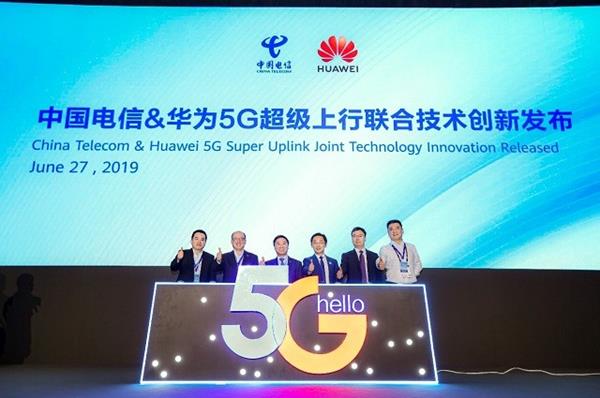
Huawei and China Telecom Jointly Release 5G Super Uplink Innovation Solution
As a large number of new pre-standard 5G services emerge, they are posing higher requirements on the uplink rate and latency. During MWC2019 in Shanghai, China Telecom and Huawei jointly released the 5G Super Uplink Joint Technology Innovation solution to accommodate those applications.
The 5G Super Uplink solution proposes the innovative networking technology featuring TDD/FDD coordination, high-band/low-band complementation, and time/frequency domain aggregation, which achieves an unprecedented uplink rate of 5G networks and reduces latency over the air interface. This solution truly redefined 5G networks based on industry requirements.
At the “Hello 5G Encouraging the Future” 5G Innovation Cooperation Conference held in April this year, China Telecom formulated the networking strategy that depends on the standalone (SA) networking and applies three SA features of URLLC, eMBB, and eMTC to meet 2B/2C requirements. China Telecom has extensively explored 5G applications in vertical industries such as government affairs, transportation, ecosystem, party building, healthcare, tourism, policing, Internet of Vehicles (IoV), education, and manufacturing. In the future 2B/2C ecosystem, large bandwidth and low latency are the focus of services. For example, the 4K HD video backhaul will give rise to the boom of new media, Internet celebrity live broadcast, and other services, bringing immersive experience to the audience. Drone services, unmanned driving, and telemedicine have higher requirements on the uplink rate and network latency.
The 5G Super Uplink solution proposed by China Telecom and Huawei implements the time-frequency domain aggregation of TDD and FDD in the uplink frequency band. Therefore, the solution can increase uplink spectrum resources of NR, boost the uplink capability of the 5G network, reduce latency, and improve the utilization rate of the uplink spectrum of 2.1 GHz/1.8 GHz. At the launch event, the Proof of Concept (PoC) of “Super Uplink” was demonstrated. The test results showed that the experienced uplink rate of 5G UEs in the cell center was increased by 20% to 60%, the experienced uplink rate of 5G UEs at the cell edge was increased to 2 to 4 times, the air interface latency was reduced by about 30%, and the URLLC services were enabled. Huawei Balong 5000 chipset, customer-premises equipment (CPE), and Mate 20 X were also displayed at the event. Super Uplink is supported from end to end by Huawei 5G technologies.
Liu Guiqing, executive vice president of China Telecom Group Co., Ltd., said: “The five ecosystems extend to 5G and become the important engine for China Telecom’s continuous growth. China Telecom adheres to the philosophy of “Customer First, Attentive Service”, insists on formulating standards first and leading technology development, and pioneers the practice of 5G network innovation. To provide better 5G experience, optimize customers’ service awareness, and enhance differentiated competitiveness in the market, China Telecom cooperates with Huawei to propose the innovative 5G networking technology featuring TDD/FDD coordination, high-band/low-band complementation, and time/frequency domain aggregation. This solution aims to further improve the uplink data capability and reduce latency, providing better development space for vertical industry applications. China Telecom will work with industry partners to seek the optimal network experience solution and promote the prosperity of the industry.”
Ryan Ding, executive director, CEO of the Carrier BG of Huawei Technologies Co., Ltd., commented: “5G not only changes everyday life but also revolutionizes human society. Service requirements are driving the development of 5G technologies. 5G industry innovation represents uplink ultra-large bandwidth, ultra-low latency, end-to-end slicing, and mobile edge computing (MEC). Based on the digital requirements of the industry, Huawei and China Telecom proposed the 5G Super Uplink Joint Technology Innovation solution. It is another breakthrough after Huawei CloudAIR solution.”
Yang Chaobin, president of 5G Product Line, Huawei Technologies Co., Ltd., noted: “The Super Uplink solution can meet the service requirements of large bandwidth and low latency at the same time. We are honored to work with China Telecom to implement the test and verification of 5G Super Uplink. Huawei 5G supports end-to-end Super Uplink and co-deployment of NSA and SA. Huawei will help industry partners continuously innovate to create the optimal 5G experience.”
China Telecom and Huawei continue to cooperate closely in technological innovation, promote 5G innovation, and contribute to 5G industry development. Huawei will support the strategic goal of China Telecom’s 5G development as always, and deepen cooperation on Super Uplink to help China Telecom take the lead in the new era of a 5G intelligent world.
Contact:
Nash Chong
[email protected]
Reference:
……………………………………………………………………………………………………………………………………………………………………………………

Philippines’ Globe Telecom to deploy “Air Fiber 5G” this month
Globe Telecom has made the Philippines the first country in Southeast Asia to offer commercial “5G” fixed wireless internet. The rollout of these services, from early July 2019, form part of Globe’s efforts to connect two million homes across the Philippines by 2020.
The at home ‘Air Fiber 5G’ postpaid plans that Globe has released offer Filipinos the option of high bandwidth and low latency services, especially given the challenge of rolling out fiber optic cables across the country.
“The arrival of 5G has caused excitement in the global world of telecommunications,” said Ernest Cu, president and CEO of Globe Telecom. “Today, we made a crucial step in fulfilling our goal of connecting more Filipino homes, and our vision of bringing first-world Internet to the Philippines,” Cu added.
The Globe At Home Air Fiber 5G postpaid plans will offer fiber-like speeds up to 100Mbps. Super-sized data packages of up to 2 terabytes will be initially available in select areas in Pasig, Cavite, and Bulacan.
Globe at Home Air Fiber 5G will be available to eligible customers in July 2019. Plans come at P1899 per month for up to 20Mbps, P2499 for up to 50Mbps and P2899 for up to 100Mbps. All come with up to 2TB data capacity.
“Prior to Air Fiber 5G, we have aggressively utilized fixed wireless solutions to connect more homes and businesses to the internet over airwaves,” said Cu. “This strategy resulted in home broadband subscriber base increasing by 55.1 per cent to 1.7 million in the first three months of 2019 from 1.1 million in the same period in 2016.”

The Globe At Home Air Fiber 5G modem
………………………………………………………………………………………………………
“Globe At Home Air Fiber 5G makes use of fixed location wireless radios instead of fiber optic cables which enables the company to go over the circuitous approval process of deploying a fiber optic cable – a task which proves to be arduous and involves securing multiple permits from local government units (LGUs),” Cu said.
“The right of process can sometimes take years to obtain, causing drastic delays in fiber optic roll-out completion,” Cu added.
Alberto de Larrazabal, Globe’s chief commercial officer, told reporters in the Philippines that Globe would use Huawei’s equipment, including radios and modems, to deliver “5G quality broadband internet.”
[Huawei and Finland’s Nokia were Globe’s equipment providers for its 4G-LTE service.]
Cu said that the company has been spending over 21% of its annual total revenues to upgrade and expand its telecommunication and IT infrastructure since 2012. “We have been ramping up our capital spend from P20.3 billion in 2012 to P43.3 billion in 2018, in order to provide our customers better broadband services,” he said.
Editor’s Notes:
- The Philippines ranks 107th among 178 countries in fixed broadband speed at 19.55 megabits per second (Mbps) versus the global average of 59.6 Mbps. Among 140 countries, it ranks 107th in terms of mobile internet speed at 15.10 Mbps, nearly half of the 27.22 Mbps global average.
- Globe is owned by Philippine conglomerate Ayala Corp, with Singapore Telecommunications Ltd holding a minority stake.
……………………………………………………………………………………………….
References:
https://www.globe.com.ph/about-us/newsroom/consumer/globe-at-home-air-fiber-5g.html
https://www.bworldonline.com/globe-launches-first-5g-service-in-southeast-asia/