

AI-Era Cloud Network Transformation: A Reference Architecture and Implementation Roadmap
By Shazia Hasnie, PhD
Introduction:
The physical network infrastructure that underpins cloud computing was designed for an era that no longer exists. Distributed training across hundreds of thousands of GPUs, real-time inference at the edge, and autonomous agent coordination impose requirements that traditional cloud network designs were never intended to meet. The networks that served the cloud era were architected for north-south traffic, best-effort delivery, and human-scale applications. None of these assumptions hold for AI.
This article presents a framework for transforming cloud network infrastructure for the AI era. It is organized around two components: a four-pillar reference architecture that defines what must be built, and a five-phase implementation roadmap that defines how to execute the transformation. Together, they provide infrastructure transformation leaders with a complete program for preparing their organizations’ physical network infrastructure for the age of AI.
The Four-Pillar Reference Architecture:
The physical network infrastructure for AI-era cloud computing is organized around four interdependent pillars. Each pillar groups related layers of the infrastructure stack. Each depends on the pillars that precede it and enables the pillars that follow.
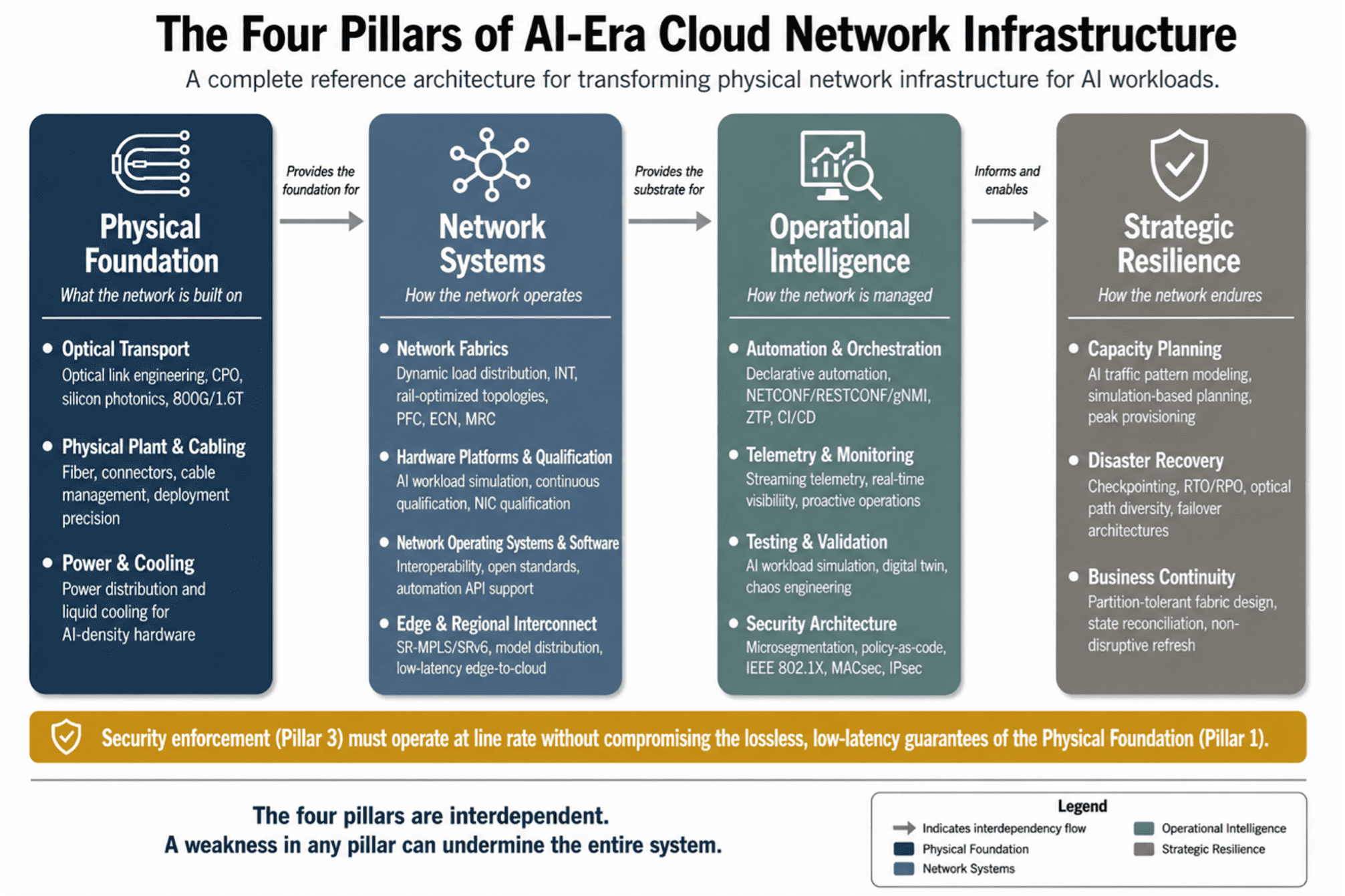
Figure 1: The Four Pillars of AI-Era Cloud Network Infrastructure — a complete reference architecture for physical network transformation.
PILLAR 1: PHYSICAL FOUNDATION
The physical foundation is the literal infrastructure on which all higher-layer network services depend. Optical transport determines the bandwidth, latency, and reliability of every interconnection between data centers, regions, and compute clusters. Physical plant and cabling provide the fiber, connectors, and cable management that make connectivity possible. Power and cooling provide the electrical and thermal infrastructure that keeps everything running.
Optical Transport. Optical link engineering for AI workloads requires a fundamental shift from traditional practice. Traditional optical link engineering treats traffic surges as anomalies and provisions for average utilization. AI workloads generate synchronized, high-bandwidth bursts—checkpointing incast can saturate multiple optical links for minutes at a time—that demand link budgets engineered for peak synchronized demand. The cost of insufficient capacity is not degraded optical performance; it is stalled training runs.
The optical technology roadmap is being reshaped by AI requirements. Co-packaged optics (CPO) integrate the optical engine directly with the switch ASIC, reducing power consumption by 30-50% while increasing port density. Silicon photonics leverage semiconductor manufacturing to produce optical components at scale. 800G and 1.6T per wavelength will be required as GPU bandwidth scales. Linear drive optics remove the digital signal processing from the optical transceiver, reducing power and latency. Breakout optics enable multi-planar topologies where each GPU connects to multiple parallel fabrics. Organizations must ensure that today’s optical investments are forward-compatible with these technologies.
Physical Plant and Cabling. Deployment precision at the physical layer determines whether the architectures designed at higher layers function as intended. Rail-optimized topologies depend on perfect physical cabling—a single miscabled port breaks the single-hop guarantee. Automated cabling verification, where the management interface validates each connection against the reference design, has reduced deployment time by up to 90% for early adopters. Continuous monitoring must detect cabling degradation before it causes performance issues.
Power and Cooling. AI network hardware consumes significantly more power than traditional cloud hardware. A rack of switches populated with 800G pluggable optics can consume over 10 kilowatts. CPO engines may require direct-to-chip liquid cooling. The transition to liquid cooling has implications that extend beyond the network—chilled water systems, heat rejection, building structural load—and retrofitting liquid cooling into a data center designed for air cooling is significantly more expensive than incorporating it into new construction.
PILLAR 2: NETWORK SYSTEMS
Network systems translate the physical foundation into functional network services. Modern data centers operate multiple physical networks—front-end, back-end, storage—each optimized for a specific traffic class. AI training demands a dedicated high-bandwidth, low-latency fabric for GPU-to-GPU communication that must interoperate with existing networks through well-defined interconnection points.
Network Fabrics. AI workloads generate east-west traffic that behaves differently from anything traditional cloud networks were designed to handle. It is dominated by a small number of high-bandwidth elephant flows—sustained, predictable data streams between GPU pairs—that produce synchronized bursts at predictable intervals. Worst-case path latency determines the completion time for collective communication operations, making the performance of the slowest path more important than average performance.
The industry has developed two distinct architectural paths to meet these requirements. For scale-up networks within a single rack or GPU pod, where distances are measured in meters and the cost of a stall is immediate, lossless transport via Priority-Based Flow Control (PFC) and Explicit Congestion Notification (ECN) remains the dominant approach. For scale-out networks connecting GPU clusters across data center halls or buildings, the industry is moving toward efficient utilization with low tail latency through fast recovery rather than absolute loss prevention. The Ultra Ethernet Consortium’s Ultra Ethernet Transport (UET) specification leads this effort, treating packet loss as a recoverable event rather than a failure.
The choice between paths is governed by three criteria: scale of deployment (≤256 GPUs favors lossless; ≥512 GPUs favors low-loss), workload characteristics (tightly coupled training benefits from lossless; loosely coupled inference tolerates low-loss), and organizational maturity (deep PFC expertise extends lossless viability to larger scales).
Four fabric capabilities support both paths. Dynamic load distribution—flowlet switching and packet spray—replaces static Equal Cost Multi-Path (ECMP) with congestion-aware path selection. In-band network telemetry (INT) provides the microsecond-granularity congestion visibility that makes intelligent load distribution possible. Rail-optimized topologies provide single-hop GPU-to-GPU connectivity for the most latency-sensitive collective operations. Advanced transport protocols, add selective retransmission via SACK and NACK that serves both scale-up and scale-out deployments.
Hardware Platforms and Qualification. Hardware must be qualified under AI workload conditions, not standard benchmarks. A switch that performs well under steady-state testing may exhibit unacceptable packet loss under synchronized burst patterns. The qualification process must answer a specific question: will this hardware maintain performance under the traffic patterns that AI workloads generate? Qualification is continuous—a firmware update, a new optics module, or a configuration change can alter behavior and must be validated before reaching production. The endpoint NIC plays a critical role, handling RDMA at line rate, packet-spray reordering, and selective retransmission. NIC qualification must be part of the same AI workload simulation process as switches and optics.
Network Operating Systems. The NOS must support PFC, INT, dynamic load distribution, and automation APIs. Interoperability is an architectural requirement in inherently multi-vendor AI infrastructure. Organizations should prioritize platforms that adhere to open standards—UET specifications, IETF YANG data models, OpenConfig—over proprietary extensions that create long-term supply chain constraints.
Edge and Regional Interconnect. AI inference increasingly occurs at the edge, requiring low-latency connectivity to cloud reasoning agents. Traffic engineering via Segment Routing over MPLS (SR-MPLS) and SR over IPv6 (SRv6) enables explicit path specification for latency-sensitive flows. Model distribution to edge endpoints requires versioned, efficient distribution protocols. Regional interconnect must be treated as a production input, not a shared utility—it is part of the AI supercomputer’s backplane.
PILLAR 3: OPERATIONAL INTELLIGENCE
Operational intelligence provides the control systems that make the network operable at scale. The AI-ready network cannot be managed through manual processes—a single AI cluster may contain thousands of switches requiring consistent configuration, where a single misconfigured buffer can stall thousands of GPUs.
Automation and Orchestration. The architectural response is declarative intent-based automation. The operator declares the desired network state using IETF YANG data models, and the automation framework translates this into device-level configuration via NETCONF, RESTCONF, and gNMI. Zero-touch provisioning enables switches to self-configure from the moment of installation. Configuration-as-code ensures every device conforms to architectural standards, with drift detected and corrected automatically. Network changes move through CI/CD pipelines that validate against policy and test under AI workload conditions before production deployment.
Telemetry and Monitoring. INT captures per-packet, per-path metrics at microsecond granularity. Streaming telemetry replaces polled monitoring with continuous, event-driven data push. The telemetry platform must ingest, store, and analyze millions of data points per second, enabling cross-layer correlation—tracing a GPU-level stall back through the fabric to the specific optical port and wavelength where the loss occurred. Predictive models detect performance degradation before it causes packet loss, shifting operations from reactive to proactive.
Testing and Validation. A dedicated testing environment must replicate production AI workload patterns—synchronized bursts, collective communication operations, checkpointing incast. Fault injection and chaos engineering validate network behavior under failure conditions. A digital twin of the production network, continuously synchronized, within a bounded delay, with real-time telemetry, enables what-if analysis for topology changes, capacity additions, and configuration updates before production deployment.
Security Architecture. Distributed AI dissolves the traditional network perimeter. The architectural response is in-fabric security: microsegmentation at the switch level validates every flow at the point of ingress, policy is bound to workload identity rather than network location, and the enforcement architecture relies on IEEE 802.1X, MACsec, and IPsec. Policy-as-code manages security rules through the same CI/CD pipelines as network configuration. The immutable audit trail serves double duty as both the security record and the compliance record.
PILLAR 4: STRATEGIC RESILIENCE
Strategic resilience ensures the network survives disruptions, scales with demand, and sustains itself over the long term.
Capacity Planning. Traditional capacity planning, based on historical averages and steady-state utilization, systematically underprovisions for AI. AI traffic is bursty, synchronized, and high-volume by design. Capacity must be provisioned for peak synchronized demand. Simulation-based planning models proposed network designs under projected AI workloads, identifying bottlenecks in the design phase before hardware is committed.
Disaster Recovery. AI training runs lasting weeks or months cannot be restarted from scratch. The network must support checkpointing at AI scale, with Recovery Time Objectives (RTO) and Recovery Point Objectives (RPO) defined per workload. The optical backbone must provide physically diverse paths with automatic protection switching. Failover architectures—active-active or active-passive—must be designed at the network level for inference workloads requiring high availability.
Business Continuity. The network fabric must tolerate WAN partitions without cascading failures, with local control planes capable of independent operation at each site. State reconciliation architecture—based on the shared event log pattern—must preserve causal ordering across partition boundaries. The network must support non-disruptive infrastructure refresh, with redundant paths and hitless failover enabling component replacement without interrupting workloads that run continuously for weeks or months.
The Five-Phase Implementation Roadmap
The migration from legacy to AI-ready network infrastructure is a multi-phase program that must deliver value at each stage while building toward the target architecture. Each phase has defined activities, deliverables, and success criteria. Each phase delivers measurable value before the next begins. Phase durations are calibrated for a Tier-1 cloud services provider; individual organizational timelines may vary based on scale, complexity, and resource availability. The success criteria stated for each phase are drawn from industry benchmarks and practitioner experience with large-scale network transformation programs. They represent targets that are ambitious but achievable for a Tier-1 cloud services provider with dedicated transformation resources and executive sponsorship.
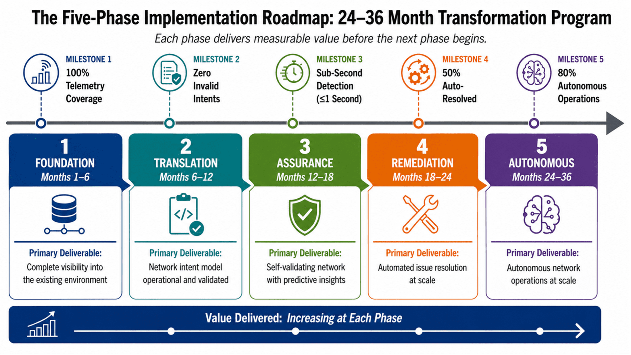
Figure 2: The Five-Phase Implementation Roadmap — A 24–36 Month Transformation Program.
PHASE 1: FOUNDATION (MONTHS 1–6)
The first phase establishes the essential building blocks. Nothing can be automated, optimized, or secured until the network is instrumented and its state is understood.
The starting point is telemetry. Streaming telemetry must be enabled across all network devices in the AI infrastructure path—switches, optics, fabric elements—using gRPC-based protocols and OpenConfig YANG data models. The deliverable is a centralized telemetry platform receiving continuous data streams from every device. The success criterion is 100% telemetry coverage. Without complete visibility, every subsequent phase operates on incomplete information.
With telemetry flowing, a topology knowledge graph must be built—a dynamic map of all devices, links, and interconnections, continuously updated from telemetry data and discovery protocols. The graph must reflect topology changes within seconds, not minutes. Accurate neighbor discovery across all fabric layers is the foundation on which intent-based automation will reason about the network.
Configuration management must be brought under version control. Every device configuration—PFC thresholds, QoS policies, dynamic load distribution parameters—must be stored in version-controlled repositories. Every change must be tracked and attributed. The success criterion is 100% configuration version control with no out-of-band changes permitted. An automation framework that deploys configuration changes cannot operate reliably if changes are also being made through manual processes that bypass the automation pipeline.
Finally, the foundational intent model must be established. This is a structured format for expressing network intent—topology, capacity, QoS policies—in machine-readable YANG-based models. The deliverable is five foundational intents, defined and validated against the existing network state:
- Lossless Transport Intent: “All Remote Direct Memory Access over Converged Ethernet (RoCE) traffic on the AI fabric shall receive PFC priority treatment with zero packet loss under sustained load.”
- Fabric Capacity Intent: “The AI fabric shall maintain a minimum of 30% headroom on all east-west links during peak utilization.”
- Optical Link Diversity Intent: “Every GPU cluster shall have at least two physically diverse optical paths to its checkpoint storage.”
- Configuration Compliance Intent: “All device configurations shall match version-controlled templates. Any deviation shall be detected and flagged within 60 seconds.”
- Telemetry Coverage Intent: “Every device in the AI network path shall stream telemetry data. Any device that stops streaming shall be flagged within 30 seconds.”
These five intents are scoped to be achievable within Phase 1 while covering the most critical dimensions of AI network operations: lossless transport, capacity, resilience, configuration compliance, and observability.
PHASE 2: TRANSLATION (MONTHS 6–12)
The second phase builds the machinery that translates intent into device-level configuration. This is where declarative automation becomes operational.
The centerpiece is the intent compiler—a translation engine that converts YAML or JSON intent specifications into device-level configuration via NETCONF, RESTCONF, and gNMI. The intent compiler is not merely a template engine. It must understand the capabilities and constraints of each target device, select the appropriate protocol for each configuration operation, and handle the transactional semantics that make configuration changes safe. The success criterion is that the five foundational intents from Phase 1 are compiled and deployed without manual intervention.
Before any compiled configuration reaches production, it must be validated in a digital twin—a virtual replica of the AI network, continuously synchronized with production telemetry. The digital twin enables what-if analysis: if this configuration is applied, what happens to fabric utilization, PFC pause events, and flow completion times? The success criterion is 100% of configuration changes validated in the digital twin before production deployment.
Validation checks must be automated. Every intent must pass feasibility validation (can the network support this intent given current capacity?), capability validation (do the target devices support the required features?), and policy validation (does this intent comply with security and operational policies?). The success criterion is zero invalid intents deployed to production.
Multi-domain support must be enabled. The intent compiler must support both data center fabric and optical backbone domains, translating a single intent into coordinated configurations across domains.
PHASE 3: ASSURANCE (MONTHS 12–18)
The third phase closes the loop between intent and reality. The network may be configured correctly at a point in time, but AI workloads cause continuous change—congestion patterns shift, optical performance degrades, buffer utilization fluctuates. Assurance ensures the network remains in its intended state.
Real-time telemetry monitoring must track SLA compliance for all AI network services, updated continuously from streaming telemetry rather than periodically from polled data. Sub-second detection latency for SLA deviations is the success criterion. A RoCE stall that lasts 500 milliseconds must be detected while it is happening, not after the training run has been disrupted.
Drift detection must compare the intended network state against the actual state continuously. Drift can take many forms: a configuration change applied outside the automation pipeline, a performance degradation that violates the intent without changing the configuration, a topology change due to a link failure. The success criterion is 99% detection accuracy for both configuration and performance drift.
The assurance dashboard must provide all stakeholders—network operations, compute operations, capacity planning—with real-time visibility into network state versus intent. Alerting must be integrated with the incident management system so that 100% of SLA breaches generate alerts within one second of detection.
PHASE 4: REMEDIATION (MONTHS 18–24)
The fourth phase enables the network to respond to drift and failures. Detection without response is observation without action. Remediation closes the loop.
Root cause analysis (RCA) must be automated. When drift is detected, the system must correlate telemetry data across layers—optical, fabric, device—to identify the source. A packet loss event at the GPU layer may originate from a congested optical link three hops away. The RCA engine must trace the event across layers. The success criterion is greater than 80% accuracy for common incident types.
At least three remediation types must be implemented and validated in the digital twin before production enablement: rollback to the last known good configuration, traffic rerouting around congested or failed links, and dynamic QoS adjustment.
A policy engine must govern which remediation actions are fully automated, which require human approval, and which are prohibited. The policy framework must be machine-readable, version-controlled, and enforced at the automation layer. The success criterion is 100% of automated remediation actions comply with defined policies.
Supervised remediation must enable a human-in-the-loop approval workflow for actions that exceed the automated threshold. The goal is that 50% of detected issues are resolved automatically without human intervention, with the remainder escalated for approval.
PHASE 5: AUTONOMOUS (MONTHS 24–36)
The final phase extends over 12 months—longer than the preceding phases—because full autonomy is not a single deployment event. It requires progressive expansion of automation scope, validation of continuous optimization across diverse workload patterns, and accumulation of sufficient operational data for the learning system to deliver meaningful accuracy improvements. Each increment of autonomy must be earned through demonstrated reliability.
The automation scope must be expanded to cover all common incident types identified and validated in Phase 4. The success criterion is that 80% of all incidents are resolved automatically. The remaining 20% represent novel failures, complex multi-domain incidents, or situations where policy requires human judgment.
Continuous optimization must become a background process. The network self-tunes PFC thresholds based on observed congestion patterns, adjusts dynamic load distribution policies as workload distributions shift, and reallocates buffer resources as traffic characteristics evolve. The success criterion is a 20% reduction in SLA violations compared to the Phase 3 baseline.
Cross-domain coordination must achieve full automation for standard intents. When a new GPU cluster is provisioned, the orchestration layer coordinates optical link provisioning, fabric configuration, and security policy establishment across domains without manual intervention. Human involvement is reserved for novel or high-risk changes.
The learning system must improve from experience. Machine learning models trained on historical incident and remediation data must increase root cause analysis accuracy over time. The success criterion is a 10% quarterly improvement in RCA accuracy.
COEXISTENCE: RUNNING LEGACY AND AI-READY NETWORKS IN PARALLEL
The transformation cannot be accomplished through a flag-day cutover. The existing cloud network must continue to operate and generate revenue throughout the transition. The AI-ready network is deployed as a separate physical infrastructure—dedicated optical links, dedicated fabric, dedicated switches—wherever possible. Physical separation eliminates the risk that AI workload traffic patterns will disrupt legacy services. Where physical separation is impractical, logical isolation with strict QoS enforcement provides the necessary workload separation. Interconnection points between the two networks must be engineered with the same packet loss, latency and throughput requirements as the AI-ready network. Operational processes must govern both environments simultaneously during a transition measured in years.
ORGANIZATIONAL TRANSFORMATION
The AI-ready network cannot be operated by a team trained only on legacy network operations. Three new skill domains become critical: AI workload literacy (understanding the traffic patterns and failure modes of distributed training and inference), telemetry and data engineering (building and operating streaming telemetry platforms and correlation engines), and automation engineering (designing and operating intent-based automation and CI/CD pipelines). The talent strategy must balance retraining existing engineers—many of the required skills are extensions of existing knowledge—with external hiring for skills that cannot be developed internally in the required timeframe. Retention of critical talent during the transformation is essential: the engineers who understand the legacy infrastructure are essential to the coexistence strategy.
FINANCIAL MODELING
Network investment for AI must be justified on value generation—the network cost per training run completed, per inference served, per GPU-hour utilized—not traditional cost efficiency metrics. This shift from cost-per-bit to value-per-outcome transforms the investment conversation. A network that costs more per gigabit but enables higher GPU utilization generates a return that far exceeds its cost premium. The five-phase roadmap enables investment to be spread over 24 to 36 months, with each phase delivering measurable value before the next begins. The cost of inaction must be quantified and presented alongside the cost of transformation.
CONCLUSIONS:
The physical network is no longer a utility layer that can be taken for granted. It is the foundation on which AI performance depends. The optical backbone determines whether GPU clusters operate at full utilization or sit idle. The network fabric determines whether distributed training completes in days or weeks. The automation and telemetry infrastructure determines whether issues are detected proactively or discovered after customer impact.
The four-pillar reference architecture defines what must be built. The five-phase implementation roadmap defines how to execute the transformation. Together, they form a complete program for infrastructure transformation leaders.
The technologies described here are deployed and operational in production AI networks today. The challenge for infrastructure leaders is not whether these approaches work, but how to adapt them to their organization’s specific constraints, scale, and timeline.
REFERENCES:
[1] TM Forum, “Autonomous Networks: Business Requirements and Framework,” TM Forum IG1251, 2025. [Online].
[2] AMD, “Next Gen Networking Transport for Large Scale AI Training,” May 2026. [Online].
htt
[3] Tolly Group, “Dell Networking Data Center AI Switch Fabric Congestion Mitigation Evaluation,” April 2026. [Online].
[4] Tech Field Day, “Cisco AI Networking Cluster Operations Deep Dive,” November 2025. [Online].
htt
[5] Akamai / WWT, “East-West Is the New North-South: Rethink Security for the AI-Driven Data Center,” February 2026. [Online]. htt
[6] NIST, “Zero Trust Architecture,” NIST Special Publication 800-207, Aug. 2020. [Online].
[7] IETF, “Network Configuration Protocol (NETCONF),” RFC 6241, June 2011. [Online].
[8] IETF, “RESTCONF Protocol,” RFC 8040, January 2017. [Online]. htt
[9] IEEE, “Priority-based Flow Control,” IEEE Standard 802.1Qbb, 2011.
[10] IEEE, “Congestion Notification,” IEEE Standard 802.1Qau, 2010.
[11] OpenConfig, “OpenConfig: Vendor-Neutral Network Configuration and Telemetry,” [Online]. https://www.
[12] Cloud Native Computing Foundation, “gRPC: A High-Performance, Open Source Universal RPC Framework,” [Online]. https://grpc.io/
[13] Ultra Ethernet Consortium, “Ultra Ethernet Specification,” [Online]. https://
………………………………………………………………………………………………………………………………………………………….
References from IEEE Techblog:
Why Batch Pipelines Break AI Agents: The Case For Streaming-First Network Operations
The enterprise network stack is collapsing; AI’s impact; comparison with “Batch Pipelines Break AI Agents”
ABOUT THE AUTHOR:

Shazia Hasnie, Ph.D., is VP Product Strategy and Innovation at Cuber AI, focused on Agentic Network Operations. Her work explores the intersection of autonomous systems, cloud-native infrastructure, and the economic models that make AI operations sustainable at scale. She brings over 20 years of global experience in communications networks and holds a Ph.D. in Communications Engineering from the Australian National University.
6 thoughts on “AI-Era Cloud Network Transformation: A Reference Architecture and Implementation Roadmap”
Leave a Reply

Thanks for the timely article
Scale-up networks need memory semantics. RoCE is RDMA for converged Ethernet. Till now all scale-up networks are proprietary and not ethernet based. Recently multiple open standards are emerging with Ethernet like ESUN, SUE, UALINK. They all use LLR and CBFC as the base.
Scale-up needs extremely low latency and carries very high bandwidth traffic. I think ECN and PFC do not work well in that environment. Even IP traffic is also not used in this environment.”
Can you please clarify if my understanding of Scale-up networks is correct.
It is interesting to see if any vendor uses RoCE in scale-up networks.
From Perplexity.ai (my best gen AI source):
“Scale-up networks” usually means a network fabric designed to maximize bandwidth and minimize latency within a tightly coupled compute system, such as a GPU cluster or AI server domain, rather than simply adding more separate machines. In current AI infrastructure usage, it often refers to ultra-high-performance interconnects that let multiple accelerators behave more like one large system.
In the broader networking sense, scale-up means increasing capacity by upgrading the existing system rather than distributing load across more systems. For example, replacing a 1GbE switch with a 10GbE switch is a scale-up move because the same basic system becomes faster or larger.
In AI and HPC contexts, the term is used more specifically for the internal fabric connecting GPUs, memory, or compute nodes so they communicate with very low delay and high throughput. Some vendors also describe this as a compute fabric, back-end network, or memory-semantic fabric.
Practical distinctions:
-Scale-up network: make one system or tightly coupled cluster bigger/faster, with very low-latency communication.
-Scale-out network: add more systems and distribute the workload across them.
Thank you for the comment. Let me clarify a few points, as there appears to be some confusion between GPU interconnects and network architecture—two distinct layers that serve different purposes and co-exist in production AI clusters today.
Proprietary NVLink is GPU interconnect. It connects GPUs within a single node. RoCE over Ethernet is a network protocol. It connects nodes to each other across racks and pods. A production AI cluster can use both simultaneously: Nvidia’s NVLink for intra-node GPU-to-GPU communication, RoCE for inter-node communication across the network fabric. They are complementary, not competing.
The term “scale-up” in the networking community refers to rack-scale Ethernet interconnects—the network layer. IEEE, IETF, and the Ultra Ethernet Consortium all use the term in this sense. The article addresses this layer. Proprietary GPU interconnects are outside its scope.
On your question about RoCE adoption: RoCE is widely deployed by every major cloud provider for rack-scale GPU networking. It is not used for intra-node GPU interconnects, where NVLink operates. These are different layers with different requirements, and the industry deploys both.
The emerging standards you mention—UALink, ESUN, SUE—operate at the interconnect layer. However, they are extending to larger domains. They represent the industry’s move toward open alternatives to proprietary GPU interconnects. These standards are not available for production deployment yet. They do not replace RoCE or Ethernet for rack-scale networking in the foreseeable future. They address a different problem at a different layer.
I hope this clarifies the distinction. It’s an important distinction for readers navigating this space.
Excellent article. I particularly liked how it separates the reference architecture from the implementation roadmap, making the transformation much more practical and actionable.
One thought that came to mind while reading it is the role of orchestration. As AI workloads increasingly span multiple clouds, regions, and edge locations, orchestration becomes the glue that brings together networking, compute, storage, and telemetry. In my view, it will be a key enabler for truly autonomous AI infrastructure.
From Perplexity.ai:
Modern orchestration must act as a multi-objective optimizer, balancing latency, cost, energy, and reliability across domains with networking becoming a first-class input.
In AI infrastructure, the network is no longer an opaque transport layer. Orchestration systems must incorporate:
-Real-time topology awareness (fabric congestion, inter-region latency, optical path availability)
-Data locality and movement costs (especially for large model checkpoints and datasets)
-Service-level intent (e.g., tail latency for inference vs. throughput for training)
For example, distributing a large model training job across regions may appear compute-efficient, but if interconnect bandwidth is constrained, synchronization overhead can dominate. An intelligent orchestrator will instead co-locate tightly coupled workloads or dynamically adjust parallelism strategies.
Data gravity and storage orchestration:
AI pipelines are increasingly data-centric, and orchestration must manage:
-Dataset placement across tiers (edge, regional, core data centers)
-Caching strategies for inference workloads
-Consistency vs. performance trade-offs in distributed storage
A practical illustration: edge inference systems (e.g., for autonomous systems or real-time video analytics) require local model shards and cached embeddings. Orchestration must decide when to refresh these from centralized repositories versus retraining locally with incremental data.
Telemetry-driven closed-loop control:
The defining shift toward autonomy comes from closed-loop orchestration, where telemetry continuously informs decision-making:
-Infrastructure telemetry: GPU utilization, memory bandwidth, network queue depth
-Application telemetry: model accuracy drift, inference latency distributions
-Environmental signals: power availability, thermal constraints
These inputs feed AI-driven control loops that can:
-Migrate workloads preemptively (e.g., before congestion or failure)
-Scale inference endpoints based on demand bursts
-Trigger retraining when model performance degrades
This is where orchestration begins to resemble autonomic networking, aligning with concepts long discussed in telecom (e.g., self-optimizing networks).
Cross-domain orchestration architecture- Modern orchestration must therefore act as a multi-objective optimizer, balancing latency, cost, energy, and reliability across domains.
Networking becomes a first-class input:
In AI infrastructure, the network is no longer an opaque transport layer. Orchestration systems must incorporate:
-Real-time topology awareness (fabric congestion, inter-region latency, optical path availability)
-Data locality and movement costs (especially for large model checkpoints and datasets)
-Service-level intent (e.g., tail latency for inference vs. throughput for training)
For example, distributing a large model training job across regions may appear compute-efficient, but if interconnect bandwidth is constrained, synchronization overhead can dominate. An intelligent orchestrator will instead co-locate tightly coupled workloads or dynamically adjust parallelism strategies.
Data gravity and storage orchestration:
AI pipelines are increasingly data-centric, and orchestration must manage:
-Dataset placement across tiers (edge, regional, core data centers)
-Caching strategies for inference workloads
-Consistency vs. performance trade-offs in distributed storage
A practical illustration: edge inference systems (e.g., for autonomous systems or real-time video analytics) require local model shards and cached embeddings. Orchestration must decide when to refresh these from centralized repositories versus retraining locally with incremental data.
Telemetry-driven closed-loop control:
The defining shift toward autonomy comes from closed-loop orchestration, where telemetry continuously informs decision-making:
-Infrastructure telemetry: GPU utilization, memory bandwidth, network queue depth
-Application telemetry: model accuracy drift, inference latency distributions
-Environmental signals: power availability, thermal constraints
These inputs feed AI-driven control loops that can:
-Migrate workloads preemptively (e.g., before congestion or failure)
-Scale inference endpoints based on demand bursts
-Trigger retraining when model performance degrades
This is where orchestration begins to resemble autonomic networking, aligning with concepts long discussed in telecom (e.g., self-optimizing networks).
Cross-domain orchestration architecture. To support this, orchestration evolves into a layered architecture:
-Global orchestrator: sets policy, intent, and high-level optimization goals across clouds and regions
-Domain orchestrators: manage local clusters, edge sites, or network segments
-Resource controllers: interface with compute (GPUs), network (SDN controllers), and storage systems.
-Standardized APIs and intent models become critical, particularly in multi-vendor, multi-cloud environments—echoing challenges seen in 3GPP and ETSI MANO frameworks.
In practical terms, orchestration becomes the “control nervous system” of distributed AI—integrating signals, making decisions, and executing actions across a heterogeneous, global infrastructure fabric.
The orchestration challenge becomes particularly acute in the hybrid model that most large organizations are moving toward—training on-premises, burst capacity in the cloud, inference at the edge. Each environment has its own orchestration toolchain, its own resource model, its own operational cadence. The orchestration layer that spans these environments is the architectural problem that the industry is just beginning to address seriously.