

SK Telecom is 5G market leader after one year of 5G service in Korea
SK Telecom today announced its 5G milestones achieved over the past year since launching the world’s first 5G service on April 3, 2019, along with its plans going forward.
According to the (South) Korean Ministry of Science and ICT released in January 2020, SK Telecom has established itself as the leader in the 5G market with around 2.22 million subscribers and 44.7% market share. With its strong performance in 5G, SK Telecom continues to maintain the unrivaled market leadership it secured since launching the 2G service in (South) Korea.
 Photo courtesy of SK Telecom
…………………………………………………………………………………………………………
SK Telecom has increased customers’ 5G experience and acceptance by creating around 70 5G Clusters* in key commercial districts and densely populated areas throughout the nation. To date, around 1 million customers visited 5G Clusters to experience differentiated 5G services including ‘Jump AR Zoo’ and ‘5G LoL Park.’
*5G Clusters are built with more base stations than other 5G coverage areas to offer optimal 5G environment for services like AR and VR.
……………………………………………………………………………………………………
Highlights:
- Since launching the world’s first 5G service on April 3, 2019, the company continues to maintain its leadership in the Korean mobile market backed by 44.7% 5G market share
- Over the past year, the company expanded its business to new areas by leveraging its strength in 5G
- SK Telecom also pronounced its plans to offer the best 5G services through hyper-collaboration
- Its plans include delivering new customer experience through mobile cloud gaming services, mixed reality contents and quantum-safe mobile devices; expanding enterprise business such as 5G MEC-based cloud business and 5G smart factory; and strengthening its 5G network by building more 5G Clusters and expanding 5G network coverage
According to SK Telecom’s analysis on 5G subscribers, people in their 30s and 40s are taking up 53% of the company’s total 5G subscriber base, which is significantly higher than the proportion of people in their 30s and 40s in total LTE subscriber base, which currently stands at 32%.
The total amount of data consumption of SK Telecom’s 5G subscribers reached 62,000 TB on average per month over the past three months (Dec. 2019 ~ Feb. 2020). During the same period, the average monthly data usage of subscribers who switched devices from LTE to 5G has increased about twofold from 14.5 GB (LTE) to 28.5 GB (5G) per person.
SK Telecom’s 5G subscribers are found to be using media services, which generally require greater speeds and bandwidths, much more actively than LTE subscribers. As of February 2020, 5G subscribers are using 7 times more VR services, 3.6 times more video steaming services and 2.7 times more game apps than LTE subscribers.
Moreover, armed with its strong capabilities in 5G, SK Telecom has successfully expanded into new business areas. The company is cooperating with Microsoft and Amazon Web Services in the area of cloud, and has ventured into the U.S. next-generation broadcasting (ATSC 3.0) market with Sinclair Broadcast Group.
SK Telecom also shared its experience and knowhow in 5G with other mobile operators across the globe including Deutsche Telekom, Taiwan Mobile and IT&E.
Going forward, SK Telecom aims to earn the title of the world’s best 5G service provider through hyper-collaboration with strong global companies. At CES 2020, SK Telecom’s President and CEO Park Jung-ho suggested “Hyper-Collaboration” with diverse Korean ICT companies to achieve innovations in areas including artificial intelligence.
For consumers, SK Telecom will focus on providing differentiated 5G services that innovate user experience through borderless collaboration with diverse ICT companies including cloud service providers, device manufacturers and telecommunications companies.
SK Telecom will continue to work closely with Microsoft to prepare mobile cloud streaming games and will also open ‘Jump Studio,’ a mixed-reality content production facility.
SK Telecom and Microsoft are currently providing 92 different games through Project xCloud. Cloud gaming service is being highlighted as the ‘game changer’ that will shift the paradigm in the gaming industry by enabling users to play high quality, premium games anywhere, anytime by accessing the cloud server.
Jump Studio will provide solutions that enable the creation of 3D content like holograms by combining the technological strengths of augmented and virtual reality technologies. SK Telecom expects Jump Studio to accelerate the popularization of realistic media by significantly reducing time and cost for content creation.
SK Telecom plans to release mobile device applied with global leading quantum cryptography technologies and provide advanced security solutions to 5G users.
In B2B, SK Telecom announced its vision of expanding the enterprise business in full scale by marking 2020 as the first year of its B2B business. To this end, the company will work closely with companies of diverse industries to serve as a catalyst for industrial innovations in Korea.
SK Telecom plans to build 5G MEC (Mobile Edge Computing) Centers in 12 different locations across Korea to lead a cloud-driven industrial revolution. To this end, the company is preparing to launch nationwide 5G edge cloud service by joining hands with global leading cloud companies such as Amazon Web Services and Microsoft.
5G edge cloud, once commercialized, will provide ultra-low latency connectivity for services like unmanned delivery robots and telemedicine, thereby bringing unprecedented changes to all industries including manufacturing, distribution and healthcare.
Moreover, SK Telecom plans to deploy a private 5G network at SK Hynix’s semiconductor manufacturing facility to realize 5G smart factory that can lead to a supercycle in the semiconductor industry. The company is planning to add cutting-edge ICT including AI video analytics and AR technology to its 5G network.
SK Telecom is also cooperating with Korea Hydro & Nuclear Power (KHNP) to realize 5G smart power plant. It will first upgrade real-time drone monitoring system for dams, remote water level monitoring system, and situation sharing system by applying private 5G network and quantum cryptography technologies to KHNP’s hydro-electric/ pumped storage power plant.
Furthermore, the company will continue to work closely with Seoul Metropolitan Government to accelerate the C-ITS (Cooperative Intelligent Transportation System) project by applying Road Learner, which consists of 5G ADAS (Advanced Driver Assistance System) and Live HD Map Update solution. 5G ADAS and Live HD Map Update solution are key technologies for autonomous driving as 5G ADAS improves driving safety through features including lane departure warning and forward collision avoidance, and Live HD Map Update solution reflects road situations to HD maps in real time.
In 2020, SK Telecom will bring the total number of its 5G Clusters to 240 and expand 5G coverage to neighborhoods (‘dong’) of 85 cities nationwide by working closely with telecommunications equipment manufacturers.
The company will also secure indoor coverage for a total of 2,000 buildings, including not just airports, department stores and large shopping malls but also small-to medium-sized buildings, by applying its sophisticated 5G in-building solutions.
“SK Telecom was able to secure new business opportunities ahead of others by achieving the world’s first 5G commercialization,” said Ryu Young-sang, Vice President and Head of MNO Business of SK Telecom. “We are confident that the 5G business models to be launched this year will drive the company’s growth over the next decade.”
………………………………………………………………………………………………………….
About SK Telecom:
SK Telecom is Korea’s leading ICT company, driving innovations in the areas of mobile communications, media, security, commerce and mobility. Armed with cutting-edge ICT including AI and 5G, the company is ushering in a new level of convergence to deliver unprecedented value to customers. As the global 5G pioneer, SK Telecom is committed to realizing the full potential of 5G through ground-breaking services that can improve people’s lives, transform businesses, and lead to a better society.
SK Telecom boasts unrivaled leadership in the Korean mobile market with over 30 million subscribers, which account for nearly 50 percent of the market. The company now has 47 ICT subsidiaries and annual revenues approaching KRW 17.8 trillion.
For more information, please contact [email protected] or [email protected].
Media Contact
Yong-jae Lee
SK Telecom Co., Ltd.
(822) 6100 3838
………………………………………………………………………………………………….
Local carriers SK Telecom, KT and LG Uplus had initially launched limited 5G commercial services in December 2018 as part of an agreement with the ICT ministry to launch simultaneously to avoid excessive competition. SK Telecom, KT and LG Uplus initially offered the 5G service in limited areas in Seoul.
Highlights of Heavy Reading’s 5G Network Operator Survey
5G Deployment Timelines & Services (from Heavy Reading’s 5G report), Author: Gabriel Brown, Principal Analyst, Mobile Networks & 5G, Heavy Reading
Key Findings:
• On a 2-year view, 41% of respondents said “faster end user speeds” is the primary driver for 5G, up from 33% in Heavy Reading’s 2019 survey. Over a 5-year view, the ability to “address new markets & services” climbs to first place in the ranking, with 42%. Operators appear to see 5G technology investment as focused on evolving their current service strategies in the near term and becoming more ambitious in the medium term.
• Heavy Reading asked when operators think more than 25% of their subscriber base will have a 5G device. 50% of respondents expect this to be the case by the end of 2022, up slightly from 45% in our 2019 survey. This looks like a bullish view at first glance, but it is in line with Omdia’s independent estimate of 28% 5G penetration in the U.S. during the same timeframe.
• Over a 3-year view, operators expect some differences between their 4G and 5G service portfolios, but not major ones. 43% said their company will offer a “very similar services portfolio” while a comparable 45% believe their portfolio will offer “mostly common services, with some 5G-only services.” Only 8% expect to offer “many 5G-only services.”
As was the case in the 2019 survey, Heavy Reading asked respondents to identify the primary drivers for 5G deployment over 2- and 5-year time horizons.
On a 2-year view, the large st group (41%) said “faster end user speeds” is the primary driver for 5G, up from 33% in 2019. “Addressing new markets and services” comes second with 28%. “System capacity and efficiency” (16%) and “competitive reasons” (16%) bring up the rear, both with reduced support relative to our 2019 survey.
These results fit with how operators tended to market 5G in 2019 – namely, on downlink speed and gigabit performance claims.
Over a 5-year view, the ability to “address new markets and services” climbs to first place in the ranking at 42%, significantly above all other scores. Operators clearly see 5G investment as focused on how advanced technology capabilities can be translated into compelling services over
the medium term.
“ULTRA-RELIABLE LOW LATENCY COMMUNICATION (URLLC) SERVICES ARE ONE OF THE DEFINING FEATURES OF 5G. URLLC REQUIREMENTS WERE INFLUENTIAL IN THE DESIGN OF THE 5G SYSTEM AND AIR INTERFACE.”
Editor’s Note:
It remains to be seen if URLLC capabilities will be finalized in 3GPP Release 16 (June 2020) and included in the first ITU IMT-2020 standard.
…………………………………………………………………………………………………..

…………………………………………………………………………………………………………….
In terms of 5G devices, 50% of respondents expect 25% or more of their subscriber base to have a 5G-compatible handset by the end of 2022. At first glance, this looks like a bullish view, and it is up slightly from Heavy Reading’s 2019 survey. This positive view on 5G adoption perhaps reflects better knowledge of, and greater confidence in, 5G device and chipset development timelines. It also possibly echoes analyst upgrades to 5G device estimates made by research firms across the board in 2019 and widely reported in the media.
For example, the result is in line with Omdia’s independently produced estimate of 28% 5G penetration in the U.S. during the same timeframe. A critical factor is handset replacement cycles for smartphones, which have lengthened in most developed markets in the past few years. In some markets – like China and South Korea – there is evidence that 5G can drive an acceleration in handset upgrades. But this is not a universal phenomenon; for instance, there is not yet good evidence of this in Europe and the U.S.
This may be because first-generation 5G devices tend to come with compromises (e.g., on power consumption, cost, and bugs). Looking into 2020 and 2021, newer handset models at high- and mid-tier prices will become available in volume. For example, a 5G iPhone – rumored for late 2020 – will be important, particularly in the U.S., where iPhone market share is high. As established earlier, over a 5-year view, operators see 5G addressing new markets and driving advanced services (Fig 7). sought insight into the differences between 5G and 4G service portfolios over a 3-year view.
A fair summary would be that operators expect some differences, but not major ones. A large 43% said their company will offer a “very similar services portfolio” for 4G and 5G users, while a comparable 45% believe their portfolio will offer “mostly common services, with some 5G-only services.” Only 8% expect to offer “many 5G-only services.”
In part, this result may reflect that 5G deployed in non-standalone (NSA) mode makes existing 4G services faster rather than fundamentally different. As discussed later, it may be that a transition to standalone (SA) is a prerequisite for service innovation.

Telecom data traffic in Cuba grows 10% due to COVID-19; Free access to EnZona e-commerce platform
Cuba state owned telecom company ETECSA president Mayra Arevich posted on her Twitter account @MayraArevich on Thursday:
“The traffic growth for (last) three days is more than 10% of additional volume on our networks”

The ETECSA official also urged not to use large volumes of data on the mobile network so that the traffic capacity can be shared among all, after noting that navigation requires seven times more resources than voice calls.
“To think as a country is to maintain the stability of our systems to guarantee services to our population. We advise you not to use large volumes of data on the mobile network, so that the traffic capacity can be shared among all,” said the executive president of the state enterprise, Mayra Arevich, quoted by the official Cubadebate site.
These (voice calls) guarantee the fundamental communications with the emergency services and our health system,’ Arevich wrote in another tweet quoted Friday by Cuba’s Granma newspaper after social media were flooded with requests for the telephone company to lower rates.
ETECSA guarantees voice/data network stability at this time of constant surveillance on the coronavirus pandemic, with which more than 465,000 people have already been infected in 200 countries, she said.

Cuba Communications Minister Jorge Luis Perdomo said this Thursday that the measures to fight coronavirus were conceived with integrity.
On Friday, Mayra Arevich Marín tweeted: “Starting today, March 27, 2020, you can access the #EnZona platform, an e-commerce application, which together with #Transfermóvil are the forefront of computerization in our society, free of charge.”


Nikkei Asian Review: Apple to delay 5G iPhone, but no opportunity lost
Apple will likely delay the launch of its first 5G iPhones, originally scheduled for September, as the coronavirus pandemic threatens global demand and disrupts the company’s product development schedule, sources familiar with the matter have told the Nikkei Asian Review.
The company has held internal discussions on the possibility of delaying the launch by months, said people familiar with the matter, while supply chain sources say practical hurdles could push back the release till 2021.
“Supply chain constraint aside, Apple is concerned that the current situation would significantly lower consumer appetite to upgrade their phones, which could lead to a tame reception of the first 5G iPhone,” said a source with direct knowledge of the discussion. “They need the first 5G iPhone to be a hit.”
Nikkei said that Apple had set an aggressive target for the release of a 5G iPhone for this September, instructing mobile suppliers to prepare to make up to 100 million units of the new devices for 2020 and designing four different models of the handsets.
Apple is closely monitoring the coronavirus outbreaks in the U.S. and Europe, its two largest markets that together account for more than half of its sales, and assessing whether a delay is necessary, the sources told Nikkei.
All of the employees at Apple’s headquarters are working from home indefinitely, as the company is subject to the Santa Clara County and the California state-wide “shelter in place” order, which requires all workers at non-essential businesses to stay at home (and tele-work if possible). The exact timetable for the 5G iPhone launch might not be finalized till that order is lifted, one of the sources said (and that could be sometime in June according to KCBS radio commentators).
“Apple will make a final decision around May at the latest, given the fluid situation globally,” another person told Nikkei.
The engineering development of the 5G iPhone has also been affected by travel curbs introduced in the U.S., China and elsewhere to combat the coronavirus, two people with knowledge of Apple’s schedule said. The company was supposed to work with suppliers to develop a more concrete prototype for the new phones from early March, but it had to delay such close collaboration, which requires hands-on testing, indefinitely.
Suppliers have not been officially notified of a possible change in the production timeline, and Apple is even urging many of them to make up for time lost due to coronavirus-related disruptions.
“We are not giving it up yet. We are doing whatever we can to sort the issue out,” a person with direct knowledge of the matter told Nikkei.
“The discussion is still at an early stage, and the fall launch is not completely off the table,” one of the sources with direct knowledge of the issue said. “But the 5G iPhone could be postponed to 2021 in the worst-case scenario.”
Suppliers agree that given where the company is in the engineering process, the possibility of a delay is looming. Some component suppliers, moreover, have told Nikkei that they have been instructed to defer their mass production schedule for about two to three months.
“We have been notified to start shipping in big volumes to meet Apple’s new product launch by the end of August, instead of like in previous years, when it would be sometime in June,” said a supplier of components related to printed circuit boards. “The change was made very recently, and that could imply that the mass production of the phone could also be delayed for months.”
The worst-case scenario, delaying the launch until 2021, would do more than just disrupt Apple’s roadmap for product releases.
The decision of the world’s most profitable smartphone company involves hundreds of global suppliers in the U.S., Europe, Japan, South Korea and China, Apple’s biggest manufacturing hub. Millions of production line jobs could be affected in the world’s second-largest economy during the peak production season for iPhones in the second half of the year.
“It’s a very tough decision for Apple to make,” as the ripple effect would be very big, another source familiar with the discussion told Nikkei.
“If any big tech company like Apple delay its plan for important new products … the issue could be even bigger than whether the supply chain could meet its schedule. It implies that they really see end demand weakening and the whole economy not recovering soon,” Joey Yen, an analyst with research company IDC, told Nikkei. “As of now we are still hoping everything can gradually recover to normal by the end of this year but for now the scenario is moving toward the pessimistic side, that the global economy could be significantly impacted.”
…………………………………………………………………………………………………..
Opinion:
We don’t think Apple delaying launch of a 5G iPhone will cause them to lose any significant revenue, as 5G roll-outs and upgrades will be delayed due to the coronavirus.
Moreover, 3GPP Release 16 and 17 have been delayed as we reported yesterday. We expect IMT 2020, scheduled for completion late this year, will also be delayed till mid 2021 as ITU-R WP 5D face to face meetings will be cancelled.
References:
3GPP delays Release 16 and 17 Freeze by 3 months; IMT 2020 impact unclear
3GPP delays Release 16 and 17 Freeze by 3 months; IMT 2020 impact unclear
3GPP stated on its website that the timeline for the completion of two of their upcoming releases that include 5G specifications will be delayed.
A shift of the Release 16 timeline was approved at the 3GPP March 20th TSG#87 plenary e-meetings.
- Rel-16 Stage 3 freeze now June 2020 (shifted by 3 months)
- Rel-16 ASN.1 and OpenAPI specification freeze will also be complete in June 2020 (stays as planned)
Freezing stage 3 of a 3GPP release essentially means no further functions can be added to the spec. ASN.1 refers to abstract syntax notation object identifiers maintained by ETSI.
3GPP SA Plenary Chairman Georg Mayer wrote in an email to this author:
“Whilst 3GPP shifted the R16 stage 3 freeze by three months, we kept the code freeze in June.
It is from my perspective incorrect to say that we shifted R16 by three months. Just the stage 3 freeze and the code freeze are now coinciding. This was also clearly stated in the approved discussion papers in all groups. Those are the source of information people should go to when they look for guidance.”
3GPP RAN Chairman Belasz Bertenyi wrote in an email to this author:
“The Release-16 ASN.1 and OpenAPI code freeze timeline is kept unchanged, and is still targeting June 2020.”
…………………………………………………………………………….
New 3GPP Release Timeline:
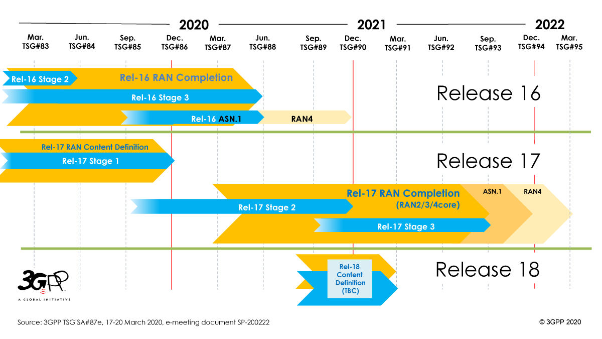
The “Release 16 Description: Summary of Rel-16 Work Items” (TR21.916) is now in production, with the Work Plan manager adding summary notes about each of the Features that it will bring, to the 3GPP system. As the Release approaches its Freeze date and completion (June 2020) – TR21.916 will start to expand and fill with useful detail about the main purpose and state of each feature.
The schedule for Release 17 is to be shifted by three months, such that the freezing of stage 3 will take place in September 2021. [Release 17 is to include further 5G system enhancements such as 5G wearables and faster network performance.] The specification freeze for Release 17 ASN.1 and OpenAPI is now scheduled for December 2021.
……………………………………………………………………………………………
The move had been expected after 3GPP announced it would cancel its face-to-face meetings in February and March due to concerns about the spreading coronavirus.
While 3GPP’s face-to-face meetings have been canceled through May, the organization has scheduled online meetings to continue its work despite the pandemic and will hopefully be able to keep their specifications on schedule going forward.
However, the impact of 3GPP’s Release 16 delay will surely push back the roll-out of true 5G deployments. It remains to be seen if the much touted but not yet completed Enhancement of Ultra-Reliable (UR) Low Latency Communications (URLLC) in 3GPP Release 16 will be submitted to ITU-R WP5D at their June 2020 meeting for inclusion in the IMT 2020 RIT/SRIT standard.
This author suspects ITU-R WP 5D leaders are looking at how to adjust their meeting plans in light of the global pandemic. Their next meeting is scheduled for June 23 to July 1, 2020 in Geneva.
Balasz says that “whatever the IMT 2020 schedule, 3GPP is continuously committed to make sure its IMT 2020 submissions will arrive in time and with high specification quality.”
………………………………………………………………………………………….
Reference:
https://www.3gpp.org/specifications/releases
…………………………………………………………………………………………..
15 April 2020 Update:
VERY IMPORTANT to note that unless it’s delayed till 2021, ITU-R IMT 2020 standard will NOT specify ultra low latency/ultra high reliability cause those capabilities are in 3GPP Rel 16 which won’t be frozen till July 3rd when their next meeting ends. ITU-R WP5D meeting ends July 1st. Hence, it will not be possible for 3GPP to submit 5G portions of Rel 16 till after WP5D’s July 1st meeting which will be too late to be included in the 1st version of IMT 2020 scheduled for late November 2020. The alternative is for WP 5D to delay their IMT 2020 completion schedule at their June-July 2020 meeting so we’ll watch that 5D meeting very closely to keep readers informed.
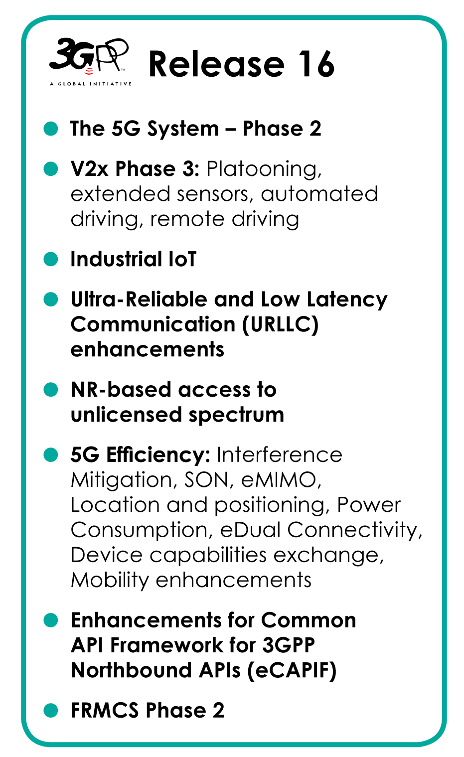
Background on Release 16:
- See the full Release 16 Description – TR21.916 (Available at Release freeze)
- RAN Rel-16 progress and Rel-17 potential work areas (July 18, 2019)
- Early progress on Rel-16 bands for 5G (April 2, 2019)
- “Working towards full 5G in Rel-16″…See a webinar presentation (July 3, 2018)
- Preparing the ground for IMT-2020
- SA1 completes its study into 5G requirements
Details of the features and work items under each 3GPP Release are kept in the corresponding, on-line, list of features and study items.
5G Patent Wars: Are Nokia’s 3,000 “5G” Patent Declarations Legit?
A Nokia press release today, Nokia announces over 3,000 5G patent declarations, the company declared more than 3,000 patent families to the European Telecommunications Standards Institute (ETSI) which were said to be “essential for the 5G standard.”
We wonder what 5G standard is that as IMT 2020 has not yet been completed? Neither has 3GPP Release 16 (5G phase 2) which when combined with Release 16 (5G Phase 1) will be the REAL (but unofficial) 5G standard.
Nokia wrote in the aforementioned press release:
With the latest declarations, the portfolio of Nokia cellular standard essential patents (SEPs) [1] declared to one or more of the 2G, 3G, 4G and 5G standards spans more than 3,400 patent families, of which more than 3,000 are relevant to 5G standards. This SEP portfolio has more than doubled in size over the past five years, with Nokia having a leading market share. Nokia Bell Labs produces the majority of these SEPs, and Nokia Technologies business manages and licenses this patent portfolio, with more than 200 licensees, including most major smartphone vendors and many automotive brands.
NOTE 1. HOW ARE SEPs DETERMINED IF A STANDARD LIKE 5G HAS NOT YET BEEN COMPLETED?
…………………………………………………………………………………………………….
Marcus Weldon, Nokia Chief Technology Officer and President of Nokia Bell Labs, said: “Nokia has defined many of the fundamental technologies used in virtually all mobile devices and digital systems and networks, and these inventions are critical to the new Industrial Internet of Things era. We standardize these inventions to allow widespread utilization and adoption. The benefits of 5G are initially in massive amounts of new capacity for consumers, but as the new technology and network architecture develops, it will enable new applications for enterprises and industrial businesses, with end-to-end 5G networks forming the critical fabric for the Fourth Industrial Revolution, with Nokia Bell Labs once again at the heart of this revolution.”
Jenni Lukander, President of Nokia Technologies, said: “I am thrilled that our R&D efforts are creating new opportunities for the consumer and industrial technology ecosystem, as the 5G era gathers momentum. As an inventor for the long-term, Nokia is able to innovate for a 5G future because of the fair reward we earn through licensing the standardized technologies created from our extensive R&D investments. This virtuous cycle creates vast new potential in 5G technologies, and I am excited for the possibilities ahead.”
Resource:
5G standards and research leadership (Nokia)
…………………………………………………………………………………………………
Comment and Analysis:
We previously reported that Samsung had licensed some of Nokia’s “5G” patents in this blog post.
Nokia’s so called “milestone” was positioned as a major step forward from the previous one six months ago declaring 2,000 patents. The clear intention was to create the impression that Nokia’s 5G R&D efforts have improved by 50% in the last six months, but it’s very difficult to verify that claim since it contains so many unknowns.
Is all that blah, blah, blah just PR or the truth? Let’s examine this 5G Patent War issue in some detail.
………………………………………………………………………………………………….
In a December 11, 2019 letter to the WSJ, Jenny Beth Martin wrote:
Nothing could be further from the truth. Qualcomm today is the undisputed leader in the 5G space for the simple reason that no other companies can keep up with the San Diego-based innovator. Qualcomm holds a staggering 140,000 patents and patent applications for 5G technologies.
………………………………………………………………………………………………………..
On March 12, 2020, Huawei was the clear leader in a European Patent Office (EPO) report titled Digital technologies take top spot in European patent applications. For the first time in more than a decade, the EPO said that digital technologies have taken the lead in patent applications filed. According to the EPO Patent Index 2019, the surge in the fields of digital communications (+19.6%) and computer technology (+10.2%) is fuelling the sustained growth in patent filings.


Statista says Huawei is leading in 5G patents. With more than 3,000 patent applications filed and more than 1,200 of these granted, Chinese manufacturer Huawei took first place in a ranking complied by IPlytics and the Technical University of Berlin.

Scott Bicheno of telecoms.com says about half of Huawei’s 5G patent applications seem to have been filed in China, and those account for half of all such applications made in China. While there’s nothing intrinsically wrong with that, it’s worth noting that Samsung and LG, which are in the top three 5G patent applicants alongside Qualcomm, have hardly filed any applications in South Korea. It’s almost as if the barrier to entry for patent filing in China is lower.
………………………………………………………………………………………………..
This author is also very skeptical about 5G patents, in light of the REALITY that many of the key 5G attributes, e.g. ultra high reliability, ultra low latency, 5G packet core, etc have not been completed yet by 3GPP.
So how can those and many other important features of “not yet completed” 5G standards be patented at this time?
Also, 5G builds on 4G-LTE so some of the so called “5G” patents might be more related to the latter.
…………………………………………………………………………………………………………
In a blog post from October 2019 titled Why you shouldn’t believe everything you read about 5G patents, Christina Petersson, CIPO and Head of IPR & Licensing at Ericsson, argues that when you apply certain essentiality filters, Ericsson is number one when it comes to 5G patents.
The patent intelligence division of the law firm of Bird & Bird, twoBirds Pattern, examined news articles and studies around 5G standard essential patents (SEPs) and found that the people writing about patents often get it wrong concerning which companies own the largest 5G SEP portfolios. They found that studies, in addition to being premature at this stage, are often over-simplistic or flawed, and that seemingly small corrections produce dramatically different results.
…………………………………………………………………………………………………..
Bicheno concludes:
That this patent war is being waged in Europe probably isn’t a coincidence either, as that is the primary battleground in the geopolitical battle of wills between the US and China. Every time a European country refuses to ban Huawei that represents a win for the Chinese state and its belt-and-road strategy of economic imperialism.
The fact remains, however, that nearly all of the patent announcements being chucked out there are largely meaningless given the lack of qualification and context attached to them. Most patent applications made now won’t be processed for around four years, and it’s only then that we’ll know who the 5G technology leader is. Until then the industry would be well advised to take any such claims with a big pinch of salt. We certainly will.
It’s quite clear that heavy cross-licensing, patent litigation, and patent pooling generate billions of dollars of legal liability and 5G will spark new and unpreceded patent wars that will dwarf previous ones.
………………………………………………………………………………………………..
References:
https://telecoms.com/503274/5g-patent-chest-beating-is-an-unhelpful-distraction/
https://www.wsj.com/articles/qualcomm-5g-security-and-patent-wars-11576096074
https://www.iplytics.com/wp-content/uploads/2020/02/5G-patent-study_TU-Berlin_IPlytics-2020.pdf
ITU Global Resiliency Platform to keep information networks ‘safer, stronger’ throughout COVID-19 pandemic

ITU Tweet March 23, 2020:
Global Network Resiliency Platform to help countries + industry cope with the increasing stress put on global networks during the #COVID19 crisis itu.int/en/mediacentre#REG4COVID
Telecommunication networks have never before been as vital to “our health and safety, and to keep our economy and society working” as they are during the current crisis, where millions are being encouraged to stay put at home, the ITU chief maintained.
He has asked instructed his team to “leverage without any delay” the new platform in aid of existing networks “to help countries and industry cope with the increasing stress being put on global networks”.
“At stake is our ability, as one human family, to give health workers everywhere, the tools they need to carry out their duties, to allow all those that can to work from home, to trade online, to ensure that hundreds of millions of children and young people keep up with their studies, and to keep in touch with loved ones, wherever they are”, he detailed.
The Global Network Resiliency Platform will also share best practices and initiatives that have been put in place during the COVID-19 crisis to ensure that telecommunication services are available to the maximum extent possible.
The portal will collect relevant information and expertise on actions that telecommunication policymakers and others in the regulatory community can use to ensure that their networks serve their country’s needs.
“This new ITU platform will provide countries struggling to find appropriate solutions to ensure their networks’ resiliency with relevant and trustworthy information and expertise on how to cope with the stresses faced by their infrastructure”, assured the agency chief.
“And because time is of the essence, it will give those countries that still have time to prepare an opportunity to learn from what is being done elsewhere – from emergency spectrum reassignments to guidelines for consumers on responsible use.”
Serving initially as an informative tool, the portal will soon be expanded to provide an interactive and engaging platform for continuous sharing throughout the pandemic and beyond.
“The crisis we are in today calls for solidarity”, he spelled out. “In these uncertain times, we should not forget all those around the world who still lack access to the Internet”.
ITU has long promoted universal, reliable and affordable connectivity, and will continue to push on all these fronts and advocate until everyone is connected.
“I call on all ITU members, from the public and private sector alike, to come together to build the best platform we can so that information and communication technology can help defeat COVID-19 and make us safer, stronger and more connected,” concluded the ITU Secretary-General.
………………………………………………………………………………………………..
Coronavirus Portal Updates:
References:
China Telcos Lose Subscribers; 5G “Co-build and Co-share” agreement to accelerate
Decrease in China’s Mobile Subscribers:
China’s wireless carriers are reporting substantial drops in subscribers as the coronavirus crisis reduces business activity.
China Mobile Ltd., the world’s largest wireless carrier, reported its first net decline since starting to report monthly data in 2000. China Mobile subscriptions fell by more than 8 million over January and February, data on the company’s website show.
China Telecom Corp. said it lost 5.6 million users in February, while China Unicom Hong Kong Ltd. subscribers fell by 1.2 million in January.
The across the board China subscriber slump indicates that the coronavirus pandemic crisis, which first emerged in China late last year, is crimping growth, even at businesses that provide essential services and earn monthly revenue. ARPU will likely also decline, according to analysts.
Chris Lane, an analyst at Sanford C. Bernstein & Co said that part of the decrease in wireless subscribers could be due to migrant workers — who often have one subscription for where they work and another for their home region — canceling their work-region account after the virus prevented them from returning to work after the Lunar New Year holidays which began in late January.
While the drop in users is unusual, the total is small relative to total wireless subscriptions, which have risen to a combined 1.6 billion for the three carriers. Things may improve starting this month as work in factories and other businesses in China resumes, Lane said.
Net income fell 9.5% last year at China Mobile, partly on government mandates to cut prices and improve service, but also due to a spike in financing costs – up from RMB144 million ($20.2 million) to RMB3.25 billion ($460 million).
The company, which reported earnings last week, told analysts revenue would remain stable this year, a sign management was not worried about the fall in subscribers.
China Unicom overcame flat revenue growth to post an 11.1% increase in net earnings for 2019. The state-owned telco slashed opex by 22% and marketing cost by 5% to record a 11.3 billion yuan ($1.6 billion) full-year profit.
“In 2019, the domestic telecommunications industry development experienced a short-term pain with weak revenue growth and pressure on industry value,” Chairman and CEO Wang Xiaochu said.

………………………………………………………………………………………..
Co-build and Co-share Agreement:
In September 2019, China Unicom entered into a cooperation agreement with China Telecom to jointly build one 5G access network across the country. China Unicom would be doubling it’s own 5G network coverage, bandwidth, capacity and transmission speed, providing users with better experience.
China Unicom said it will actively step up the “co-build and co-share” with China Telecom in areas such as 4G indoor distributed antenna systems, server rooms, optical fiber and pipelines to further enhance network advantages and corporate value.
References:
https://www.bnnbloomberg.ca/china-s-mobile-carriers-lose-15-million-users-as-virus-bites-1.1410626
https://www.telecomlead.com/5g/china-unicom-reveals-5g-network-capex-plans-94530
AT&T boosts wireless network capacity in spectrum-sharing deal with DISH Network
DISH Network is loaning AT&T 20 MHz of spectrum in the AWS-4 band, as well as its entire supply of 700 MHz airwaves, for two months. This is the third spectrum-sharing arrangement that the satellite provider has made since Sunday as telecom network providers prepare for extra data traffic from people working at home.
“DISH is proud to join forces with AT&T to achieve a common, critical goal: supporting the connectivity needs of Americans during this challenging time,” said Jeff Blum, DISH SVP of public policy and government affairs, in a statement.
This follows last week’s news that DISH would lend its complete 600 MHz portfolio of spectrum to T-Mobile. In addition to loaning spectrum to T-Mobile and AT&T, DISH was given permission yesterday by the FCC to also loan spectrum to Verizon.
/cdn.vox-cdn.com/uploads/chorus_image/image/66528643/DSC_4155.0.jpg)
According to analyst Jonathan Chaplin at New Street Research, AT&T will be able to deploy the AWS-4 spectrum quickly and easily using its AWS-1 and AWS-3 equipment. In addition, AT&T can use Dish’s 700 MHz E-Block in conjunction with the D-Block that AT&T has started deploying in some markets. Analysts are speculating that these loans during the COVID-19 crisis might later be turned into ongoing leases.
Chaplin wrote: “All told, DISH has now loaned out spectrum that could be leased at an annual run rate of $940 million. They still have the PCS H-Block and another 20 MHz of AWS-4, which would be worth another $580 million.”

Chaplin of New Street says: “All we know at this stage is that DISH is helping in a crisis; we don’t know that either side would be willing to convert the loan to a lease.”
DISH’s generosity in lending its spectrum during the coronavirus scare is highlighting how helpful the spectrum is to other operators in order to increase their capacity.
Wells Fargo analyst Jennifer Fritzsche wrote, “Once this crisis passes, we believe the heavy demand on wireless and wired networks will shine the light on the need for additional spectrum allocation and continued programs to support push-out of broadband into rural areas to lessen the digital divide.”
………………………………………………………………………………….
PC Magazine has a breakdown of how Dish is distributing its unused spectrum over the next 60 days. Each provider is getting spectrum that can temporarily help bolster its 4G LTE data network and increase speeds. In AT&T’s case, Segan estimates that wireless customers could notice up to a 20Mbps uptick in data performance while the spectrum loan is in effect.
DISH has often been criticized for hoarding spectrum and not putting it to any actual use. The company even risked fines from the FCC for failing to build an actual wireless network with the spectrum it owns. But that was before the company was brought into the T-Mobile and Sprint deal and positioned as the replacement fourth “major” carrier once the merger is finalized.
Earlier today, T-Mobile issued a news release stating that the company remains prepared to close the merger with Sprint even as financial markets are in turmoil due to the coronavirus pandemic. All necessary US regulators have already approved it and the two providers emerged victorious over a challenge from several US states.
References:
https://www.fiercewireless.com/wireless/dish-lends-spectrum-to-at-t-during-covid-19-pandemic
https://www.pcmag.com/news/att-4g-gets-a-big-capacity-boost-in-coronavirus-crisis
China Mobile has 15.4 million 5G customers; 5G+ is primary focus area
China Mobile today published its 2019 annual financial report, stating that the company’s operating revenue reached CNY745.9 billion -a year-on-year increase of 1.2% – and its net profit was CNY106.6 billion ($15 billion) – a year-on-year decrease of 9.5%.
The fall in net profits was largely due to a spike in financing costs – up from RMB144 million ($20.2 million) to RMB3.25 billion ($460 million).
Operating revenue was just 1.2% higher, at RMB745.9 billion ($104.8 billion), while telecom services revenue improved by a meager 0.5%.
A few highlights:
- The largest China telecom network provider acquired 15.4 million 5G customers in the first three months after launch.
- In 2019, China Mobile’s mobile users increased by 25.21 million, reaching a total of 950 million. Its mobile Internet data traffic increased by 90.3% year-on-year and its mobile Internet DOU reached 6.7GB.
- Wireline broadband customers grew by 30.35 million to a total of 187 million.
- China Mobile’s family broadband users reached 172 million, an increase of 17.1% year-on-year. Its family broadband comprehensive ARPU reached CNY35.3.
- At the end of 2019, China Mobile’s government and corporate clients reached 10.28 million, a year-on-year increase of 43.2%. The company’s international business revenue saw a year-on-year increase of 31.4%.
![]()
Mr. Yang Jie, China Mobile’s Chairman of the Board said in the press release:
“We were faced with a challenging and complicated operating environment in 2019 where the upside of data traffic was rapidly diminishing and competition within the telecommunications industry and from cross-sector players was becoming ever more intense. Coupled with this was the impact of government policies, including the continued implementation of the “speed upgrade and tariff reduction.”
Against this backdrop, all of us at China Mobile joined together to overcome these hurdles and work towards our ultimate goal of becoming a world-class enterprise by building a dynamic “Powerhouse”. This was centred on the key strategy of high-quality development, supported by a value-driven operating system that leverages our advantages of scale to drive further convergence, integration and digitization across the board.
We structured our organization to enable effective and synergetic capability building and collaborative growth, while nurturing internal vitality. In addition, we further implemented our “5G+” plan to spearhead the development of “four growth engines”, comprising the “customer,” “home,” “business” and “new” markets. These measures have helped us obtain positive momentum in overall operating results, which was a hard-earned achievement for us in a tough year.”
Yang noted that the COVID-19 epidemic had driven more and more businesses and consumers online and encouraged greater takeup of digital and cloud-based services. “We will leverage these opportunities, as well as the 5G network, to further develop the information and communications services market.”
Business Market:
The “business” market was China Mobile’s new growth engine and we strove to nurture new growth points by fully leveraging our cloud and network convergence advantages, building on our DICT (data, information and communications technology) infrastructure comprising IDC, ICT, Mobile Cloud, big data and other corporate applications and information services. Buoyed by active promotion of our “Network + Cloud + DICT” smart services, customers and revenue recorded rapid growth.
As of the end of 2019, the number of corporate customers increased to 10.28 million, representing year-on-year growth of 43.2%.
Focusing on key sectors such as industry, agriculture, education, public administration, healthcare, transportation and finance, the company deepened go-to-market resources to promote DICT solutions that cater to sector-specific scenarios. This strategy has boosted DICT revenue to RMB26.1 billion, or growth of 48.3% year-on-year, contributing a larger portion of our overall revenue.
“5G+” Achieved a Good Start:
China Mobile sped up the development of 5G and have been fully implementing its “5G+” plan since June 2019, when we were granted the 5G licence. These initiatives have shown good initial results.
The company actively participated in setting international standards for 5G to drive technological development. It led 61 key projects in relation to 5G international standards setting and own more than 2,000 5G patents. It also helped to continuously strengthen the Standalone 5G (within 3GPP Release 15 and 16).
Its “six international standards (3GPP specifications are not standards) on 5G system architecture” and “38 international standards including 5G NR (New Radio) terminals and base station radio frequency” scooped all the top prizes in the 2019 Science and Technology Awards presented by the China Communications Standards Association, demonstrating our leadership in 5G communications standards.
At the same time, the company accelerated the implementation of “5G+” by formulating well- coordinated development of 5G and 4G. It constructed and began operating more than 50,000 5G base stations and launched 5G commercial services in 50 cities. Emerging technologies such as AI, IoT (Internet of Things), cloud computing, big data and edge computing were assimilated into 5G (5G+AICDE) and developed more than 200 critical capabilities, while making breakthroughs in over 100 5G joint projects.
In terms of 5G+Eco, we aimed to develop the ecosystem with other industry players. Through its 5G Innovation Centre and 5G Industry Digital Alliance, more than 1,900 partners were attracted.
The 5G Device Forerunner Initiative, guiding manufacturers to launch 32 5G devices, was established. The level of maturity was basically the same between the 2.6 GHz and 3.5 GHz industry chains. Benefiting from forward-looking planning and effective execution, we expanded 5G+X, where “X” stands for the wider application of 5G, in applications that have been adopted by a plethora of industry sectors, as well as the mass market. For the latter, we launched exclusive plans for 5G customers and feature services such as ultra-high definition videos, cloud-based games and full-screen video connecting tones. As of the end of February 2020, our 5G plans attracted 15.40 million package customers – maintaining an industry-leading position.
In terms of vertical sector, China Mobile explored the possibility of combining 5G with AICDE capabilities, extending collaboration in the industry and deep-diving into classic manufacturing scenarios to develop our leadership in 5G smart manufacturing, 5G remote medical services and 5G automated mining, among other sectors. A total of 50 group-level demo application projects were implemented.
Looking ahead, 5G presents infinite possibilities. China Mobile will continue to take a systematic approach to planning and steadily implementing our “5G+” initiatives. The company will speed up technology, network, application, operations and ecosystem upgrades, accelerate industry transformation by converging technologies, integrate data to strengthen information transmission in society, and introduce digitized management to build the foundation for digital society development. By doing so, China Mobile will seek more extensive 5G deployment, covering more sectors and creating greater efficiency and social value.
…………………………………………………………………………………………….
References:
https://www.chinamobileltd.com/en/file/view.php?id=226450
https://www.chinatechnews.com/2020/03/19/26442-china-mobile-net-profit-down-9-5-in-2019
https://www.lightreading.com/asia/china-mobile-reports-154m-5g-customers/d/d-id/758329?