ZTE, China Telecom and China Unicom complete 5G co-build, co-share verification

ZTE Corporation, in partnership with China Telecom and China Unicom, has today completed the network verification based on the co-build, co-share mode in the commercial 5G environment, launching the world’s first NSA co-build co-share sites of 1.8 G/2.1 G/3.5 G in Hangzhou, China. That fully verifies the large-scale commercial capabilities of the 5G co-build co-share mode, and lays a solid foundation for greatly reducing initial investment in 5G and efficiently promoting 5G constructions.

The verification, based on the real 5G commercial network environment, covers the basic functions of network selection and anchor carrier triggering, network management functions of rights management and northbound interface in the data transmission environment, as well as multi-dimensional deep network sharing capability verification, such as multi-vendor, multi-operator mobility.

The co-build, co-share mode is capable of providing the broadband multi-operator 5G services on the same 5G base station, and reasonably allocating spectrum resources based on user requirements and service requirements. It fully demonstrates the system’s stability and outstanding performance, as well as its complete capacity for large-scale commercial use.

In addition, compared with the original construction strategy that each operator builds its own 5G networks, 5G co-build co-share sites across operators will effectively save investment in 5G networks. By promoting the sharing of infrastructure between operators, the co-build co-share mode can help operators build 5G networks with lower costs and more effective methods.

On September 9, 2019, China Telecom and China Unicom signed the 5G network co-build co-share framework cooperation agreement. As a strategic partner of China Telecom and China Unicom, ZTE fully supports their network construction and service operation. ZTE has innovatively proposed a flexible ultra-broadband spectrum application solution to support the co-build co-share mode, which helps reduce infrastructure construction costs, thereby further realizing the economic and social value of 5G.

In the future, ZTE will continue to partner with China Telecom and China Unicom to explore the applications of new 5G technologies in commercial networks, improve network quality, build more high-quality 4/5G networks, in a bid to provide users with better services.

ZTE is a provider of advanced telecommunications systems, mobile devices, and enterprise technology solutions to consumers, carriers, companies and public sector customers. As a part of ZTE’s strategy, the company is committed to providing customers with integrated end-to-end innovations to deliver excellence and values as the telecommunications and information technology sectors converge. Listed in the stock exchanges of Hong Kong and Shenzhen (H share stock code: 0763.HK / A share stock code: 000063.SZ), ZTE sells its products and services in more than 160 countries.

To date, ZTE has obtained 35 commercial 5G contracts in major markets, such as Europe, Asia Pacific, Middle East and Africa (MEA). ZTE commits 10 percent of its annual revenues to research and development and takes leadership roles in international standard-setting organizations.

……………………………………………………………………………………………………………………………………………………………….

ZTE and and Guangdong Branch of China Mobile have won Best Industry Solution Award from ICT by virtue of ZTE’s Common Edge solution at PT Expo China 2019:

Based on ZTE’s Common Edge platform, Guangdong branch of China Mobile and ZTE jointly piloted MEC edge computing services, conducting pre-commercial verification of the SA networking, construction mode, edge service application scenarios, and the cooperation mode with third parties.
ZTE’s Common Edge solution features converged access of wireless network and fixed network, which supports multiple systems  such as 4G, 5G, and WiFi, thereby building a unified fixed and mobile convergence platform.

Moreover, this solution supports cloud-based deployment and unified O&M. Embedded MEC, edge MEC and central cloud are deployed on the same base in a distribution mode. The dual-core (OpenStack+K8S) driving function provides efficient, flexible and flowing computing power, offering a unified edge cloud view and improving management efficiency. Based on AI engines, cloud-edge collaboration and edge-to-edge collaboration, the solution implements dynamic follow-up service flows and intelligent optimization of power. By means of unified management and local unattended O&M, this solution significantly reduces O&M costs.   In addition, this solution features embedded hardware in the site equipment room, such as IT BBU V9200 and TITAN C600, to implement zero-site and close-to-user deployment. With front wiring design, it is easy to maintain E5410/E5430 short chassis servers in the edge equipment room and compatible with mainstream acceleration hardware (GPU / FPGA / SmartNIC), supporting AI, image processing and video processing.

ZTE’s Common Edge solution revolutionizes the traditional closed telecom network architecture, and exposes the edge network infrastructure, hardware acceleration capability, edge network shunting capability and wireless network perception capability to the third-party applications, thereby helping various industries construct a win-win 5G ecosystem.
ZTE’s Common Edge solution has been widely used in the fields of industrial manufacturing, smart grid, Internet of Vehicles, entertainment & media, public safety, education, health, finance and agriculture. It focuses on industrial applications of wireless network capability exposure, big video, Internet of Vehicles, intelligent manufacturing and electric power. To date, by means of this solution, ZTE has carried out extensive cooperations and piloted with more than 100 strategic partners and over 200 industrial users to accelerate the penetration of 5G into various industries.
ZTE is a provider of advanced telecommunications systems, mobile devices, and enterprise technology solutions to consumers, carriers, companies and public sector customers. As a part of ZTE’s strategy, the company is committed to providing customers with integrated end-to-end innovations to deliver excellence and values as the telecommunications and information technology sectors converge. Listed in the stock exchanges of Hong Kong and Shenzhen (H share stock code: 0763.HK / A share stock code: 000063.SZ), ZTE sells its products and services in more than 160 countries.

References:

https://www.zte.com.cn/global/about/news/20191112e1.html

https://www.zte.com.cn/global/about/news/20191101e1


Posted in Uncategorized Tagged

China to launch 5G mobile networks on Friday with a huge government backed push

China’s  three major wireless carriers— China MobileChina Unicom , and China Telecom —will begin selling 5G services to consumers on Friday, November 1st in 50 major cities, including Beijing and Shanghai, said Chen Zhaoxiong, vice minister of the Ministry of Industry and Information Technology on Thursday October 31st at a Beijing conference. That will allow those with the few available 5G-China compatible smartphones to buy a subscription to access the network.  The Chinese telcos will charge by speed rather than data used. See the section on 5G Subscriber Pricing below.

……………………………………………………………………………………………………………………………………………………………………………………………………………………..

The Chinese government has made building 5G a national priority, clearing red tape and reducing costs so the three wireless providers introduce the new technology as swiftly as possible.  “They’ve made this a national priority. It’s part of the [Communist] Party‘s ability to show that it’s delivering the goods,” said Paul Triolo, head of geo-technology at the Eurasia Group consultancy. “And in the middle of the trade dispute and the actions against Huawei, it’s even more important for China to show that they are continuing to move forward despite all these challenges,” he added.

“This 5G technology is part of an overall, far-reaching revolution, and it will bring brand-new changes to the economic society,” China Telecom President Ke Ruiwen said at the launch Thursday.

China is forecast to spend between $130 billion and $217 billion on 5G between 2020 and 2025, according to a study by the state-run China Academy of Information and Communications Technology.

While some countries, such as South Korea, Australia and parts of the United States, have started 5G pilots, the Chinese government has embarked on a centrally planned push to roll out the technology on a commercial basis and give it an unassailable lead in the global race to install 5G wireless networks.

“The commercialization of 5G technology is a great measure of [President] Xi Jinping’s strategic aim of turning China into a cyber power, as well as an important milestone in China’s information communication industry development,” said Wang Xiaochu, president of China Unicom.

China President Xi has described the world as on the cusp of a fourth industrial revolution, one characterized by advances in information technology and artificial intelligence, analysts at Trivium China, a consultancy, wrote in a research note this week. “Xi wants to make sure that China is at the forefront of this new revolution — getting 5G up and running is a way to get a leg up in that race,” they said.

China’s central government wants 5G coverage extended to cover all of Beijing, Shanghai, Hangzhou and Guangzhou by the end of the year. The country’s largest carrier, China Mobile, which has 900 million cellphone subscribers, says it will be able to offer 5G services in more than 50 cities this year.  Chinese technology companies have been touting the industrial applications of 5G, such as managing cement production,  typhoon monitoring and  surgeries performed by robots.

“Two robots accurately planted 12 guide pins into the patients’ spines,” Beijing Daily reported after a surgeon manipulated robots performing operations in Shandong and Zhejiang provinces. “The signal transmission ran smoothly during the surgery without latency, despite the distance of over 1,000 miles.”
The advent of 5G could also enable some of China’s more repressive applications of technology, such as facial recognition. Travelers will be able to enjoy faster check-in with facial recognition systems at Beijing’s gargantuan new airport, a China Unicom representative said at a 5G exhibition in the capital accompanying the commercial rollout.

But there are challenges ahead.  For one, relatively few people have 5G-enabled phones or other 5G end points. Huawei has released phones that can support 5G, as have China’s Oppo and South Korea’s Samsung.  Apple, which comprises only 6 percent of the Chinese market, is not expected to release a 5G-capable iPhone until next year.

Further, there are questions about whether Huawei, the main manufacturer of base stations, can keep up its production pace now that it is on an American blacklist. The Trump administration, citing national security concerns, added Huawei and 70 of its affiliates to its entity list in May, blocking them from buying American parts and components.

“It’s going to be really hard for Huawei to overcome the supply chain problems,” said Triolo of Eurasia Group. “Basically, the United States has Swiss-cheesed their supply chain, and there are big question marks hanging over Huawei’s ability to plug the holes.”

The technology is at the heart of a bitter dispute between China and the United States. Washington has expressed concern that 5G hardware made by Chinese manufacturers might contain hidden “back doors” that could enable spying.

……………………………………………………………………………………………………………………………………………………………………………………………………………..

5G Base Stations:

Approximately 13,000 5G base stations have been installed in Beijing, the communications administration said this week.  About 10,000 are already operating.  China already has a total of more than 80,000 5G macro base stations, typically cellular towers with antennas and other hardware that beam wireless signals over wide areas, government officials said. They said China will end the year with about 130,000, while Bernstein Research estimates South Korea will be in second place with 75,000, followed by the U.S. with 10,000.  Piper Jaffray estimated that of the 600,000 5G base stations expected to be rolled out worldwide next year, half will be in China.

Indeed, Chinese operators are launching 5G across fully 80,000 macro base stations this week, a figure that will grow to 130,000 by the end of this year, according to Wall Street research firm Bernstein Research. In comparison, the firm expects South Korea to end the year in second place with 75,000 base stations, followed by the US with just 10,000.

This is why most analyst firms expect China to command the largest number of 5G customers in the years to come.

Telecom-industry executives say Chinese wireless carriers now (and in the future will) buy the most of their cellular transmission equipment from Huawei. Analysts say U.S. measures that limit American businesses from selling components to Huawei could make it more difficult for the Chinese company to make telecom equipment. Huawei says it has taken steps to minimize the impact of such restrictions.

China’s 5G Standard-Approved by ITU-R for IMT 2020 RIT:

It should be noted that China has their own 5G standard, which has been presented to and progressed by ITU-R WP5D which is standardizing the radio aspects of IMT 2020.  Here’s an excerpt of an IEEE Techblog comment:

On July 17, 2019, the ITU-R WP5D#32 meeting ended in Buzios, Brazil. At this meeting, China completed the complete submission of the IMT-2020 (5G) candidate technical solution, and obtained the official acceptance confirmation letter from the ITU regarding the 5G candidate technology solution.

China’s 5G wireless air interface technology (RIT) solution is based on 3GPP new air interface (NR) and narrowband Internet of Things (NB-IoT) technology. Among them, NR focuses on the technical requirements of enhanced mobile broadband (eMBB), low latency and high reliability (URLLC) scenarios, and NB-IoT meets the technical requirements of large-scale machine connection (mMTC) scenarios. China’s 5G technology program expresses China’s understanding of 5G technology, considers the integrity and advancement of 5G technology, and maintains the global unified standard with 3GPP as the core, reflecting China’s industrial interests.

According to the requirements of the ITU, the complete 5G technology submission materials include technical solution descriptive templates, link budget templates, performance indicator satisfaction templates, and self-assessment reports. China’s 5G technology solutions and technical support materials come from many research results of domestic equipment manufacturers, operators and research units, reflecting the collective efforts and collective wisdom in the domestic communications field. China’s self-assessment research results show that the NR+NB-IoT wireless air interface technology solution can fully meet the technical vision requirements of IMT-2020 and the IMT-2020 technical indicators.

https://techblog.comsoc.org/2019/07/17/itu-r-wp5d-brazil-meeting-imt-2020-rit-srits-from-3gpp-china-korea-advance-nufront-submits-new-rit/#comment-3673

……………………………………………………………………………………………………………………………………………………………………………………………………………..

5G Subscriber Pricing:

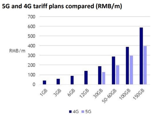
Chinese officials said the cheapest 5G subscription would cost 128 yuan (about $18) for 30 gigabytes of data a month.  To enjoy the peak speed of 1 Gbps, Unicom customers will pay about $45 a month.

According to the Wall Street research analysts at New Street Research, China Mobile is offering 5G services at a 30% discount to 4G. “A 30GB 4G customer who migrated to 5G on the same plan would see their bill reduced from RMB 188 to RMB 128. Even a 12GB 4G customer migrating to the 30GB 5G plan would save money,” the analysts wrote in a report to investors.

Source: New Street Research

10 million people in China have already registered their intention to purchase 5G subscriptions as we wrote in this IEEE Techblog post.

Mike Dano of Light Reading had this assessment:

A big part of the “race to 5G” discussion centers on spectrum allocation. Operators in China and South Korea are mainly using midband spectrum like 3.5GHz for their 5G buildouts, while operators in the US are using bands ranging from 600MHz to 28GHz because there isn’t much available midband spectrum for 5G in the US. This could change in the months to come as the FCC moves to release midband C-Band spectrum for 5G in the US. Midband spectrum is useful for 5G because it toes the line between providing high-speed connections and covering large geographic areas.

However, in recent months some US policymakers have been working to move the goalposts in the “race to 5G” a bit by pointing out that China’s 5G buildout is mandated by the country’s ruling party while 5G buildouts in the US and elsewhere are driven by the economics of competition and capitalism. As FCC Commissioner Brendan Carr explained earlier this month, that means 5G networks in the US will be more directly aligned with consumer demands than 5G networks in China.

Regardless, China’s official 5G rollout is starting this week — in a country with about four times more potential customers than the US — and it’s undoubtedly going to dwarf the 5G efforts in other countries in terms of most industry metrics.

Huawei vs Apple 5G smartphones in China:

Huawei Technologies has increased its smartphone market share in China to a record 42% in the September quarter, growing shipments by 66% year over year, while Apple’s share fell by two percentage points to 5%, with its shipments falling 28% year over year, according to Canalys.

Huawei has already released 5G-enabled phones—and they’re cheaper than Apple’s high-end non-5G iPhones. More models from other Chinese competitors will likely come out in the next few quarters. Industry analysts don’t expect a 5G-enabled iPhone until late 2020.

Rosenblatt Securities analyst Jun Zhang predicts many low- to mid-end iPhone users in China could switch to a cheaper 5G Android phone in 2020. “We believe Apple still has yet to face its biggest challenge in China, which is the upcoming launch of 5G service in November as well as the coverage for 5G service expanding to 100 cities by the middle of 2020,” Zhang wrote in a Thursday research note. “We continue to expect Apple’s smartphone market share will decline once 5G service starts in more cities,” he wrote in a note to clients.

……………………………………………………………………………………………………………………………………………………………………………………………………………..

References:

https://www.lightreading.com/mobile/5g/chinese-operators-start-selling-5g-at-a-big-discount/d/d-id/755307?

https://www.wsj.com/articles/china-is-about-to-switch-on-5g-its-behind-the-u-s-but-not-for-long-11572494203?

https://www.barrons.com/articles/chinas-5g-networks-go-live-friday-it-could-be-bad-news-for-apple-51572545922

https://www.washingtonpost.com/world/asia_pacific/showing-that-the-us-wont-hold-it-back-china-launches-commercial-5g-service/2019/10/31/4f2e64da-fb16-11e9-9e02-1d45cb3dfa8f_story.html

China’s big 3 mobile operators have 9 Million 5G subscribers in advance of the service; Barron’s: China to lead in 5G deployments

3GPP Release 16 Update: 5G Phase 2 (including URLLC) to be completed in June 2020; Mission Critical apps extended

NOTE This article is intended as a reference, which is especially important to debunk claims made about current pre-standard 5G deployments which are almost all based on 3GPP Release 15 “5G New Radio (NR)” for the data plane with LTE signaling and LTE mobile packet core (EPC) for Non Stand Alone (NSA) operation.  5G pundits continue to site 3GPP as the standards organization responsible for 5G which is doubly wrong because it’s not a standards body and submits its 5G/IMT 2020 proposals to ITU-R WP 5D via the latter organizations member entities.  As we’ve stated many times before, ITU-R is responsible for the radio standards for IMT 2020, while ITU-T is working on the non-radio aspects of IMT 2020.

………………………………………………………………………………………………………………………………………………………………………………………………………………..

Summary:

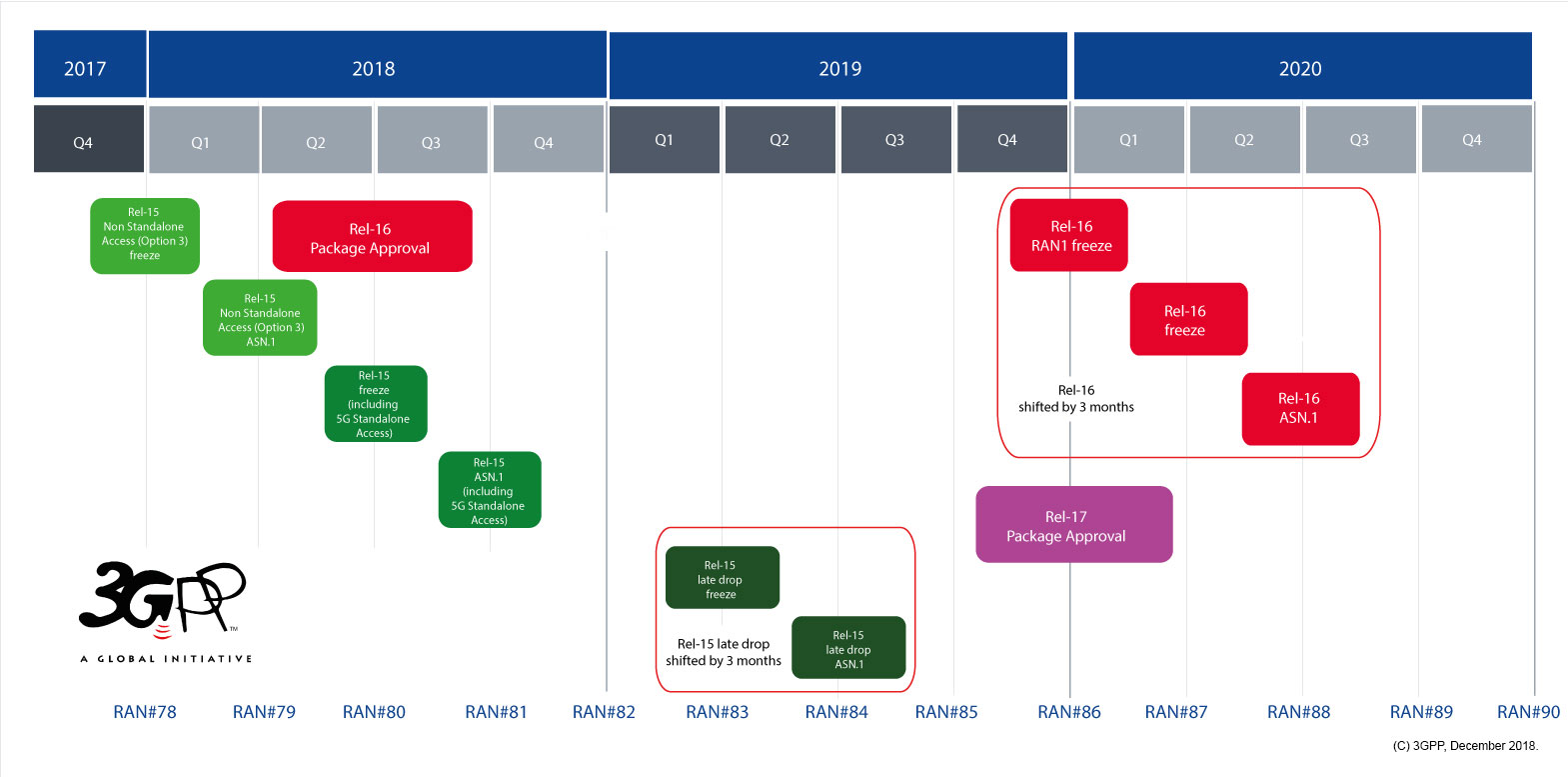
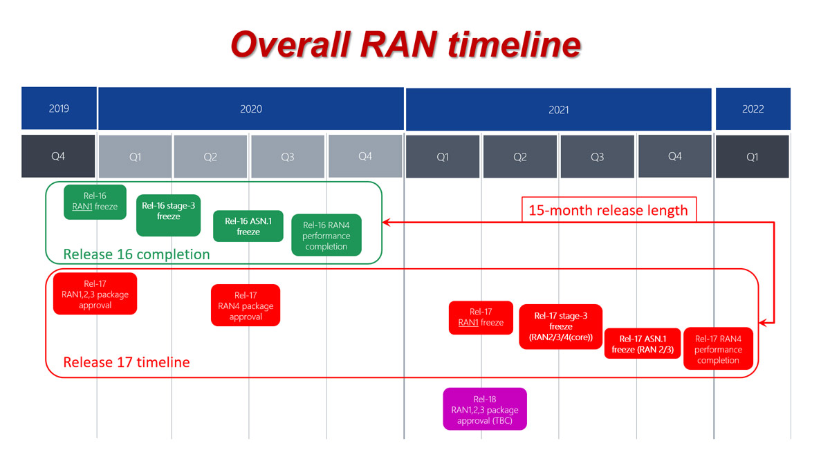
3GPP Release 16 is a major release for the project, because it will bring the specification organization’s IMT-2020 RIT/SRIT submission (to ITU-R WP 5D) for an initial full 3GPP 5G system to its completion.  Release 16 will be put in a “frozen” state in March 2020 with a targeted  completion date of June 2020.

3GPP work has started on approximately 25 Release 16 studies, which cover a variety of topics: Multimedia Priority Service, Vehicle-to-everything (V2X) application layer services, 5G satellite access, Local Area Network support in 5G, wireless and wireline convergence for 5G, terminal positioning and location, communications in vertical domains and network automation and novel radio techniques. Further items being studied include security, codecs and streaming services, Local Area Network interworking, network slicing and the IoT.

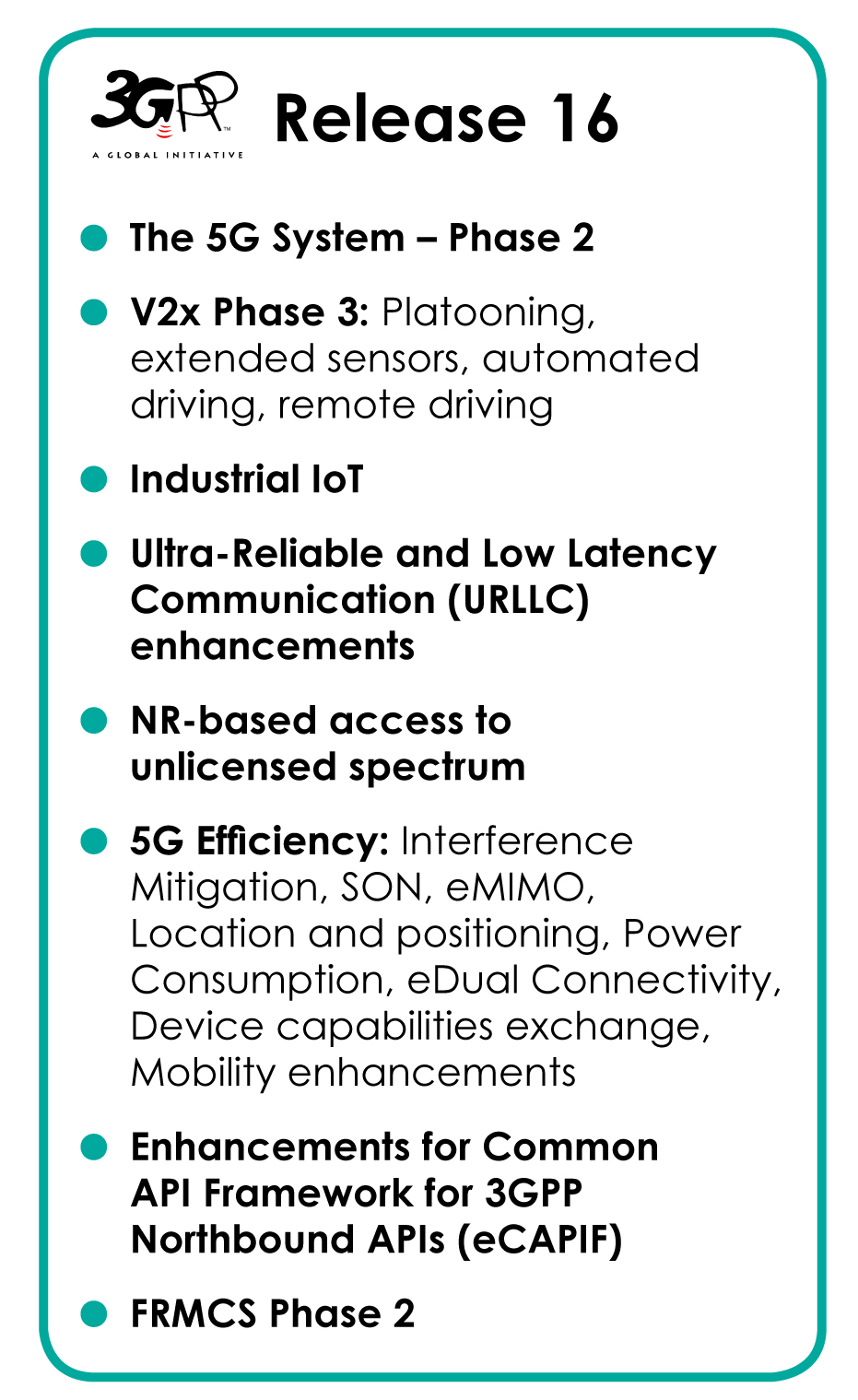
Here are the new features planned for 3GPP Release 16:

Details of the features and work items under each 3GPP Release are kept in the corresponding, on-line, list of features and study items.

  • Enhancement of Ultra-Reliable (UR) Low Latency Communications (URLLC)
  • 5GS Enhanced support of Vertical and LAN Services
  • Cellular IoT support and evolution
  • Advanced V2X support
  • 5G Location and Positioning Services
  • UE radio capability signalling optimization
  • Satellite Access in 5G
  • Enablers for Network Automation Architecture for 5G
  • Wireless and Wireline Convergence Enhancement
  • Mission Critical, Public Warning, Railways and Maritime
  • Streaming and TV
  • User Identities, Authentication, multi-device
  • (Network) Slicing
  • Other cross-TSG Release 16 Features
  • NR-related Release 16 Features
  • Release 16 Features impacting both LTE and NR
  • LTE-related Release 16 Features

R16

From 3GPP’s July 18, 2019 Webinar:

webinar ran84 slide7

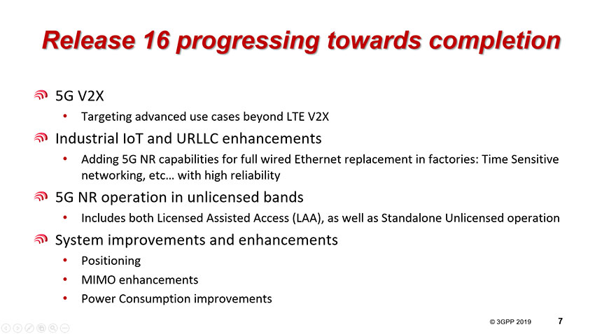
“For the (industry) verticals, there are three distinct pillars that we are focused on: Automotive, Industrial IoT and Operation in unlicensed bands. For 5G based V2X, which builds on the two iterations of the LTE-V2X, we are now adding advanced features – primarily in the area of low latency use cases.

The second focus is industrial IoT and URLLC enhancements. Factory automation, in particular, is a strong pillar for 5G going forward. We are trying to ensure that the radio side covers all of the functions that all the verticals need for factory automation. What this means in practice is that we are trying to make sure 5G NR can fully replace a wired ethernet – currently used – by adding time sensitive networking and high reliability capabilities.

The third pillar is operation in unlicensed bands. We have seen different schemes for generic 5G licensing strategies in Europe and in other parts of the World. We have seen in some countries that certain licensed bands have been allocated for vertical use cases, though that is not the case for a majority of countries. The use of unlicensed bands provides a great opportunity – where licensed spectrum is not an option. We are now focused on not only what we have with LTE, which is the licensed assisted access scheme, but also on standalone unlicensed operation – to be completed in Release 16.

Release 16 also delivers generic system improvements & enhancements, which target Mobile Broadband, but can also be used in vertical deployments – Particularly; positioning, MIMO enhancements and Power consumption improvements.”

………………………………………………………………………………………………………………………………………………………………………………………………….


Technical Reports (the result of the study phase) are also being developed on broadening the applicability of 3GPP technology to non-terrestrial radio access (initially satellites, but airborne base stations are also to be considered) and to maritime aspects (intra-ship, ship-to-shore and ship-to-ship). Work also progresses on new PMR functionality for LTE, enhancing the railway-oriented services originally developed using GSM radio technology that is now nearing end of life.

As part of Release 16, Mission Critical (MC) services will be extended to address a wider business sector than the initial rather narrow public security and civil defense services for which they had originally been developed. If the same or similar standards can be used for commercial applications (from taxi dispatching to railway traffic management, and other vertical sector scenarios currently being investigated), this would bring enhanced reliability to those MC services through wider deployment, and reduced deployment costs due to economies of scale – to the benefit of all users.

In December 2018, an adjustment was agreed at TSGs#82 – to allow a 3 month shift in the Functional freeze (of features) and the ASN.1 completion for both Release 15 and Release 16:
2019 NR schedule late drop pic3

IMT-2020 – Final submission

Release 16 will be “5G phase 2” and will be completed in June 2020 (TSGs#88) – See adjustment noted above.
Original schedule:
 imt timeplan1
This Release will meet the ITU IMT-2020 submission requirements and the time-plan as outlined in RP-172101:
Details of the work plan – to meet agreed IMT-2020 submission time plan:
Step 1: From Sep 2017 to Dec 2017, discussions in RAN ITU-R Ad-Hoc
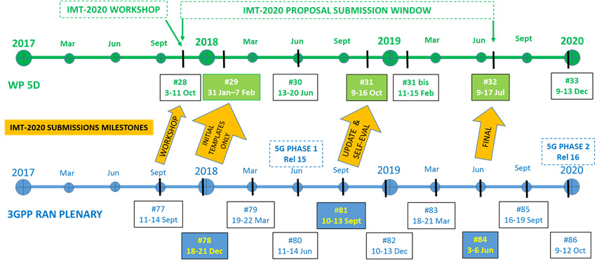
  • Calibration for self evaluation
  • Prepare and finalize initial description template information that is to be submitted to ITU-R WP 5D#29.

Step 2: From early 2018 to Sep 2018, targeting “update & self eval” submission in Sep 2018

  • Performance evaluation against eMBB, mMTC and URLLC requirements and test environments for NR and LTE features.
  • Update description template and prepare compliance template according to self evaluation results.
  • Provide description template, compliance template, and self evaluation results based on Rel-15 in Sep 2018.

Step 3: From Sep 2018 to June 2019, targeting “Final” submission in June 2019

  • Performance evaluation update by taking into account Rel-16 updates in addition to Rel-15
  • Update description template and compliance template to take into account Rel-16 updates in addition to Rel-15
  • Provide description template, compliance template, and self evaluation results based on Rel-15 and Rel-16 in June 2019.

Some Background on Release 16

……………………………………………………………………………………………………………………………………………..

References:

https://www.3gpp.org/release-16

https://www.3gpp.org/news-events/2058-ran-rel-16-progress-and-rel-17-potential-work-areas


…………………………………………………………………………………………………………………………………………………………………………………………………….

Addendum (December 14, 2020):

RAN R17 schedule

https://www.3gpp.org/news-events/2098-5g-in-release-17-%E2%80%93-strong-radio-evolution

Posted in Uncategorized Tagged

China’s telecom carriers to play a pioneering role in 5G; China Telecom and China Unicom may be barred from U.S.

by Ma Si <[email protected]> of China Daily Multimedia Co. Ltd.

Xiang Ligang, director-general of the Information Consumption Alliance, a telecom industry association, and a keen observer of the telecom sector for nearly two decades, said: “Chinese telecom companies have made big strides in their innovation capabilities, through their consistent and heavy input into research and development. They have strong willingness to pioneer cutting-edge applications.”

Four of the world’s top six smartphone makers – Huawei, Xiaomi, Oppo and Vivo – are Chinese. In 2018, the country produced 1.8 billion smartphones, accounting for 90 percent of global production, data from the Ministry of Industry and Information Technology showed.

Their decades of efforts have helped nurture the world’s largest online population in a single nation – the 854 million strong Chinese netizens (as of June). That is more than the combined population of European countries. More importantly, more than 99 per cent of netizens in China surf the internet through smartphones.


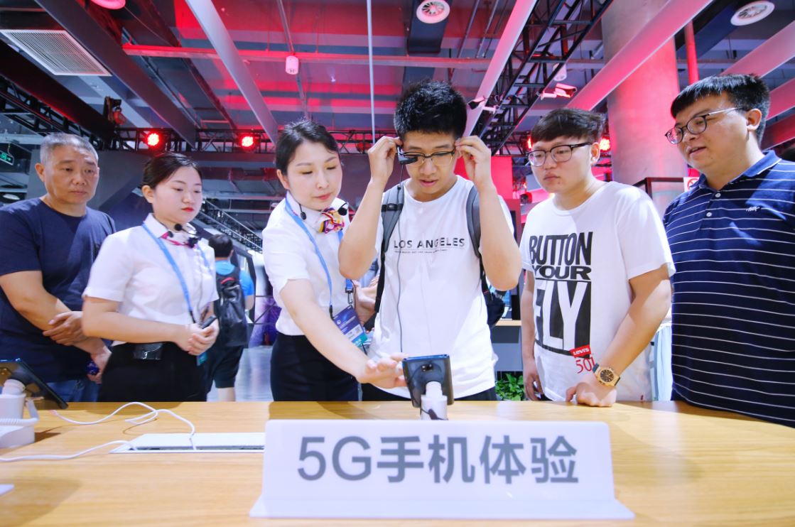
Vistors try 5G phones at an international expo on June 20, 2019. [Photo by Liu Chenghe/For China Daily]

…………………………………………………………………………………………………………………………………………………………………………………………………………………………………………………

Wu Jichuan, 82, a former head of the former Ministry of Posts and Telecommunications, said handsets are becoming almost omnipresent in the country. They can help users do almost everything from buying movie tickets, booking hospital or clinic appointments to ordering meals.

“That was in sharp contrast to 1980’s when mobile communication services were first brought to China. Back then, only successful Chinese businesspeople were able to use brick-sized, palm-filling mobile phones,” Wu recalled.

Such phones, however, were capable of just two functions: making and receiving calls. Yet, they were luxury products of the time. A handset could cost as much as about 20,000 yuan ($2,798). Consumers had to pay an extra fee of 6,000 yuan to sign up for the telecom network services. Calls cost 5 jiao a minute. In comparison, the average salary of ordinary people was no more than 100 yuan a month, Wu said.

According to Wu, one of the biggest contributions of China’s telecom industry is that it laid down a sound digital infrastructure for companies and consumers to access fast internet networks at affordable prices. They laid the foundation for China’s kaleidoscope of mobile applications and thriving digital economy.

Leveraging these achievements, the country’s telecom carriers are scrambling to establish a beachhead in the 5G era, in which almost everything can be connected to the internet.

As at the end of May, Chinese companies accounted for more than 30 percent of all patents essential to the global standards for 5G. After the country granted the commercial 5G licenses in June, local telecom carriers are working to build a sound network infrastructure to accelerate the technology’s commercialization.

Yang Jie, chairman of China Mobile, the world’s largest mobile operator, said the company plans to cover 50 cities across China with 5G signals by the end of this year.

“That will involve deploying 50,000 5G base stations across the country,” Yang said, adding that the company has already raised 7 billion yuan as the first phase of a 5G fund to promote the development of key technologies. The planned total size of the fund is 30 billion yuan.

Similarly, China Unicom said it will cover at least 40 cities with 5G signals by the end of this year and work together with all industry partners, including foreign companies, to accelerate 5G infrastructure construction.

Just a day after securing its 5G license, China Unicom announced it had opened experience stores across 40 cities to encourage consumers to try applications powered by the superfast technology.

Visitors can play with mechanical robotic arms, watch 4K high-definition live-streaming, wear virtual reality goggles to play 3-D games and learn that with 5G, doctors can complete surgeries on patients 2,500 kilometers away.

Lyu Tingjie, a telecom professor at the Beijing University of Posts and Telecommunications, said: “After all the hype about 5G, the new era has finally started. All the state-of-the-art applications are getting closer to the public than ever. The next question is: How to better time the rollout and partner with a wide range of traditional sectors to boost efficiency?”

The country’s telecom carriers are expected to spend 900 billion yuan to 1.5 trillion yuan on 5G network construction from 2020 to 2025, according to a report from the China Academy of Information and Communications Technology.

The first batch of 5G smartphones hit the market in August. China Unicom said its 5G data packages will cost a minimum of 190 yuan, arguably the world’s lowest price, in its first stage of application.

In comparison, the minimum cost in South Korea’s 5G data packages is about 325 yuan per month, while US telecom operator AT&T charges users $70 (equivalent to 498 yuan) for 15-gigabytes of 5G data every 30 days.

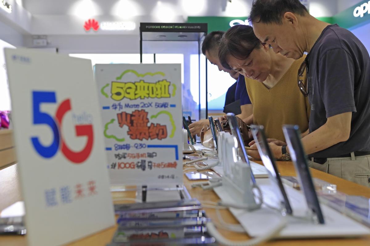
Consumers visit the booth of China Telecom as the company’s Shanghai branch launches a promotion called “Buy 5G mobile phones and enjoy 5G network.” [Photo by Ying Liqing/China News]

…………………………………………………………………………………………………………………………………………………………………………………………………………………………………………………………………………….

Meanwhile, Chinese telecom equipment makers are securing a growing number of 5G contracts to supply foreign telecom carriers. Huawei said it had signed 50 commercial contracts for 5G with carriers worldwide, with 28 contracts from Europe, 11 from the Middle East, six from the Asia-Pacific region, four from the Americas, and one from Africa.

According to a forecast by the Global System for Mobile Communications Association, an industry group, China is set to become the world’s largest 5G market by 2025, with 460 million 5G users.

……………………………………………………………………………………………………………………………………………………………………………………………………………………….

Sidebar:  Huawei

In 2003, when Huawei Technologies Co, then known more as a manufacturer of telecom equipment like switches, and base stations, decided to set up a mobile phones department, China was still using 2G, or the second-generation wireless technology.  Back then, only a fraction of consumers could use cellular phones to surf the internet. And it took them about five seconds or longer to open a web page.

Sixteen years later, Huawei is the world’s second-largest smartphone maker. Its 5G-enabled handsets can download heavy data files – say, a 1 GB movie – in seconds. That’s just a glimpse of the commercial possibilities in the 5G era, which China kicked off in June.

From a virtual non-entity in the global mobile phones market to a world-renowned company, Huawei’s rise has been meteoric, and it coincided with the development of China’s telecommunications industry.

Huawei, however, is just one of the many Chinese telecom companies that have thrived on the global stage in recent years, helping the country to transform from a follower during the period of 2G and 3G to a pioneer in the 5G era.

William Xu, a director on Huawei’s board and president of the Institute of Strategic Research, said the company has had more than 200,000 5G base stations in shipment, which marked a steady step forward, compared with its earlier announcement of 150,000 base stations in late June.

Huawei has invested about $4 billion in all so far in the research and development of 5G since 2009.Founder and CEO Ren Zhengfei has said in an interview that other players will not be able to catch up with Huawei in 5G over the next two to three years.

http://www.chinadaily.com.cn/a/201909/16/WS5d7ee28ca310cf3e3556b8d9.html

……………………………………………………………………………………………………………………………………………………………………………………………………………………….

Senators Urge F.C.C. to Review Licenses of 2 Chinese Telecom Companies:

Senator Chuck Schumer of New York along with Senator Tom Cotton of Arkansas, cited national security concerns in a letter to the FCC which asked the commission to review the licenses that giveChina Telecom and China Unicom, the right to use networks in the United States. In the letter, they said that the two Chinese government-linked telecom operators could use that access to “target” Americans’ communications. And they warned that the companies could reroute communications traveling on their networks through China. The text of the letter was obtained by The New York Times.

Brian Hart, an F.C.C. spokesman, said that Ajit Pai, the F.C.C. chairman, had made it clear that the agency was “reviewing other Chinese communications companies such as China Telecom and China Unicom” but didn’t commit to opening a formal proceeding to look at the licenses.

China Telecom denied that it represents a national security threat to the United States. China Unicom did not respond to a request for comment.

“We make the protection of our customers’ data a priority, and have built a solid reputation as one of the best telecom companies in the world,” said Ge Yu, a spokesman for China Telecom’s Americas subsidiary, adding that the company is proud of “maintaining a good standing with all regulatory agencies.”

National security officials have been worried for years that the Chinese government could use its companies to gain access to crucial telecommunications infrastructure. Those concerns have become more prominent as carriers in the United States and in China race to launch next-generation 5G wireless networks — and American regulators have targeted Chinese telecom companies in the name of security.

In May the F.C.C. denied an application from China Mobile to operate in the United States. Ajit Pai, the commission’s chairman, said at the time that there was a risk that the Chinese state would use the carrier to “conduct activities that would seriously jeopardize the national security, law enforcement, and economic interests of the United States.”

So if the FCC bans China Telecom and China Unicom it will be a trifecta ban on all three state owned Chinese telecom operators!

https://www.nytimes.com/2019/09/15/business/federal-communications-commission-china.html


………………………………………………………………………………………………………………………………………………………………………………………………………………………..


China Races Ahead of the U.S. in the Battle for 5G Supremacy + 5G to stimulate US$500B in China tech growth over next 5 years (CAICT)

Bloomberg: China Races Ahead of the U.S. in the Battle for 5G Supremacy

by Sheryl Tian Tong Lee –with assistance from Ed Ludlow (emphasis added by Alan J Weissberger)

In the race for tech supremacy, China is betting it can seize the lead by building the world’s biggest 5G wireless networks.

To get there, the country is banking on the might of the one-party state, making sure its state-run carriers have access to cheap airwaves and fast, inexpensive approvals for putting up the hundreds of thousands of base stations the fastest wireless technology requires.

As top phone companies elsewhere flinch at the cost of building 5G wireless networks, China’s operators are barreling ahead on the government’s mandate, virtually free airwaves and equipment at less than half the price U.S. carriers are paying. Being the first to reach massive scale with the speediest networks could also help the nation in its ambition to dominate industries like factory automation, robotics and autonomous driving.

“5G is a foundation and catalyst for reinventing industries,” said Paul Lee, U.K.-based head of research for technology, media and telecommunications at Deloitte Consulting. “The fundamental benefit of being the first mover is that you can build business models on the back of that and export them to other countries.”

…………………………………………………………………………………………………………………………………………………………………………………………………

South Korea’s wireless carriers were the first to offer commercial 5G services, with SK Telecom Co. launching its network in April and Samsung Electronics Co. already offering a 5G-enabled smartphone. But while U.S. carriers in cities like Minneapolis and Chicago have the beginnings of 5G offerings, it’s in sheer scale where China is on course to edge ahead over the next five years.

That size advantage is also reflected in China’s push to invent 5G technology.

The country’s biggest companies have already established a lead in patents related to the fastest network technology. Huawei Technologies Co., the contentious Chinese firm that’s at the heart of current U.S.-China tensions, leads the pack as the world’s biggest telecom equipment supplier. Meanwhile, ZTE Corp., which has also drawn America’s ire in the past, comes in at No. 3, according to Berlin-based patent information platform IPlytics.

But that won’t necessarily translate into network domination. China’s three carriers — China Mobile Ltd., China Unicom Hong Kong Ltd. and China Telecom Corp. — are all state owned.

Harvard Business School economist Shane Greenstein says having a bigger government role in 5G may not provide an advantage.  “The private firms in China in the digital sector have an admirable record with experimentation,” he said. “The state-owned enterprises? That is a more open question.”

Where the government is helping is by holding carriers’ costs down. Beijing is providing the bandwidth for 5G networks almost for free, said Edison Lee, head of telecommunications research at Jefferies Hong Kong Ltd.

U.S. carriers, by contrast, bid $2.7 billion at two auctions of 5G airwaves, according to the Federal Communications Commission. In India, the industry group representing carriers says its members can’t afford spectrum the government expects to auction for about $84 billion this year.

China’s operators will also pay less for base stations. The units will probably cost about $30,000 each in China, less than half the $65,000 average in other developed-economy markets, Jefferies’ Lee estimates. Two of China’s carriers have said they will lease the equipment, cutting the upfront cash outlay to roughly $6,500 each per year, Lee said.

In the U.S., where the government is leaving 5G to companies, carriers will also pay at least five times more than Chinese operators for civil engineering and permits to build 5G, Deloitte Consulting estimates.

The world’s most populous country has about 350,000 5G-operable base stations deployed, nearly 10 times as many as in the U.S., according to a U.S. Department of Defense study.  The report says China claiming the position of standard-setter for 5G, with Huawei leading rival telecom equipment makers, is a risk for the U.S. This “will create serious security risks for DoD going forward if the rest of the world accepts Chinese products as the cheaper and superior option for 5G,” said the report.

Concern about China’s edge prompted President Donald Trump to float a proposal last year for the government to build a secure 5G network, people familiar with the matter said at the time. The idea was dropped immediately after regulators, industry leaders and elected officials immediately pushed back, saying companies were in a better position to move the technology forward.

The idea of China securing that advantage is also stoking concern among competitors beyond the telecommunications equipment and wireless services industries.

Chip maker Qualcomm Inc., for example, is urging the U.S. and other Western governments to embrace 5G more rapidly or risk falling behind China in the potentially life-saving technology, which is also used in self-driving cars.

China will be “saving hundreds if not thousands of lives much sooner than we will as we fumble to determine which is the standard that is best for the long-term road map in the Western world,” Qualcomm Senior Vice President Patrick Little said in an interview.

While China’s autonomous driving infrastructure lags behind the U.S., where firms like Alphabet Inc.’s Waymo LLC are streaking ahead in real-world testing, Chinese companies are developing related 5G applications with some established car makers.

ZTE is conducting 5G tests on self-driving cars, and has cooperated with Audi AG’s China unit to develop “internet-of-vehicles” technology. In robotics, ZTE is working with internet giant Baidu Inc. and Siasun Robot & Automation Co. to develop 5G applications.

Byton Ltd., an electric-vehicle startup based in Nanjing, will release an SUV in China at the end of this year that includes a range of artificial intelligence functions and a roof antenna that offers data transfer rates up to 10 Gbit a second, which it says is hundreds of times the normal average bandwidth.

The benefits of setting 5G standards may also help China outside its borders. President Xi Jinping’s Belt and Road Initiative includes a push for Chinese-built network infrastructure across the length of a route that runs across Eurasia, the Middle East and parts of Africa.

“Developing countries that are more sensitive to cost will find the Chinese 5G price-point difficult to turn down, especially when the offer is sweetened with infrastructure and project-financing incentives like the Belt and Road Initiative,” the U.S. Department of Defense report said.

For its part, the U.S. is letting the private sector guide 5G development, Federal Communications Commission Chairman Ajit Pai said in a June speech to wireless executives in New York.

“For all this talk about our government’s focus on 5G, make no mistake that we are pursuing a market-based strategy to promote 5G development and deployment,” Pai said.

And the U.S.’ crackdown on Huawei, cutting it off from components made by American companies, will be a big test of China’s 5G lead, says Anthea Lai, Asia Pacific media, technology and telecommunications analyst for Bloomberg Intelligence.

“Before Huawei’s ban, China had strong potential to lead in standalone 5G,” Lai said. “But now we have to see how much Huawei can keep its carrier business intact,” she said.  “Huawei could slow China down.”

…………………………………………………………………………………………………………………………………………………………………………………..

To contact the reporter on this story: Sheryl Tian Tong Lee in Hong Kong at [email protected]

To contact the editors responsible for this story: Dave McCombs at [email protected], Jason Clenfield

©2019 Bloomberg L.P.

Original article at: https://www.bnnbloomberg.ca/china-races-ahead-of-the-u-s-in-the-battle-for-5g-supremacy-1.1296079

………………………………………………………………………………………………………………………………………………………………………………………

From South China Morning Post: 5G to stimulate US$500 billion in China tech growth over next five years

At the Global Mobile Internet Conference held in the southern coastal city of Guangzhou on Saturday, a representative from the China Academy of Information and Communications Technology (CAICT) forecast that 5G will stimulate growth in the country’s information technology industry by 3.3 trillion yuan (US$479 billion) over the next five years.  That development is expected to rev up digitization across traditional industries, which would yield more than 10 trillion yuan in growth over the same period.

………………………………………………………………………………………………………………………………………………………………………………………..

“4G has changed people’s lives,” said Chen Jinqiao, deputy chief engineer at the academy, which is under the Ministry of Industry and Information Technology (MIIT), during his presentation on China’s 5G development in the conference. But he indicated that 5G has the potential “to change society,” as different industries adopt the technology to their various requirements.

Chen’s growth estimates come amid the increased pace of 5G infrastructure spending in China, which is attempting to move ahead in the global race to deploy ultra-fast, next-generation mobile networks.

With peak data rates up to 100 times faster than what current 4G networks provide, 5G has been held out as “the connective tissue” for the Internet of Things, autonomous cars, smart cities and other new mobile applications, establishing the backbone for the industrial internet.

………………………………………………………………………………………………………………………………………………………………………………………..

References:

https://www.scmp.com/tech/big-tech/article/3020815/5g-stimulate-us500-billion-china-tech-growth-over-next-five-years

https://www.scmp.com/tech/enterprises/article/2168665/made-china-2025-5g-offers-worlds-biggest-mobile-market-chance-seize

China IT Minister: 5G Licenses Coming this Year; Deployment timing dependent on technology maturation

China Telecom to accelerate 5G deployment; 100% Fiber network coverage; Gigabit fiber broadband deployment

https://techblog.comsoc.org/tag/chinas-imt-2020-promotion-group/

http://www.imt-2020.cn/en/category/65569

https://money.cnn.com/2018/04/16/technology/china-united-states-5g-technology-study/index.html


Updated information on China’s IMT-2020 Submission

1 Introduction

At its 29th meeting of ITU-R Working Party (WP) 5D, China submitted in Document 5D/838 the initial characteristics template of the candidate technology for the terrestrial components of IMT-2020.

The initial characteristics template was based on 3GPP development, and includes the key characteristics description according to the progress in 3GPP at that time. The provided template description reflects the development of the major component, and does not preclude other component(s) that might be included in later update.

In this document, the updated information of China development towards IMT-2020 submission is provided.

2 Updated information

To complete the submission under Step 3 of the IMT-2020 process as defined in Document IMT‑2020/2(Rev.1), China is preparing the self-evaluation report, the complete set of submission template (including the updated characteristics template that captures new progress compared to the one provided in Document 5D/838, link budget template, and compliance template), and compliance with IPR policy.

The technical development of the candidate technology for the terrestrial components of IMT-2020 of China is undergoing, and China’s development and outcomes of the research of the candidate radio technologies are contributed from the members of IMT-2020 (5G) Promotion Group to 3GPP. In this context, China development is aligned with the on-going 3GPP development. According to 3GPP schedule, 3GPP Rel-15 was completed in June 2018.

The self-evaluation is also under preparation. The technical parameters and configuration parameters that applied to the candidate radio interface technology are under investigation. The detailed evaluation methodology for the technical performance requirements are under development. The outcome of these studies are also contributed to 3GPP from the members of IMT‑2020 (5G) Promotion Group. The initial evaluation parameters for eMBB are captured in Section 2 of 3GPP documents R1-1803386 and R1-1805644, respectively. And the detailed evaluation method for mobility is captured in Section 2 of 3GPP document R1-1805643. China will conduct the self-evaluation accordingly.

Editor’s Notes:

  1.  China’s IMT-2020 Promotion Group documents can be downloaded (free) here.
  2.  Detailed ITU-R WP5D China IMT2020 submission contributions are here (TIES Users only).
  3.  Key IMT 2020 results of ITU-R WP5D Oct 2018 meeting in Fukuoka, Japan:

IMT-2020 RIT submission:
This meeting received updated information related to the proposal of candidate IMT-2020 radio interfaces (RITs) from ETSI and DECT Forum (Document 5D/1046); and also updated submissions of candidate IMT-2020 radio interfaces from 3GPP (Document 5D/1050), China (Document 5D/1055), and Korea (Document 5D/1077).  These contributions were reviewed and the respective IMT-2020 documents were revised accordingly.  (No updates from India which had previously indicated it’s plan to submit).

IMT-2020 evaluation:
An initial evaluation report was received from the Evaluation Group TPCEG and reviewed. An IMT-2020 Document was created to record the evaluation report (Document 5D/TEMP/608). In addition, SWG Evaluation also started to review the received self-evaluation results from 3GPP, China and Korea.

A draft liaison statement to the Registered Independent Evaluation Groups was developed to update the work progress within WP 5D on Evaluation of IMT-2020 candidate technologies (Document 5D/TEMP/610).

3 Conclusion

China kindly invitesWP 5D to view the above information, and take them into account in Document IMT-2020/5.

China will provide the latest information related to the development of candidate radio interface technology of IMT-2020 in a timely manner.

………………………………………………………………………………………………….

Characteristics template for

Candidate Radio Interface Technology of ’NR+NB-IoT’ RIT

This characteristics template provides the description of the characteristics of the candidate IMT-2020 radio interface technology (RIT) based on 3GPP Rel-15 work. The candidate RIT is composed of NR and NB-IoT.

It is noted that new features in addition to the ones provided in this characteristics template might be included in future update for the RIT.

For this characteristics template, China has addressed most of the characteristics that are viewed to be helpful to assist in evaluation activities for independent evaluation groups, as well as to facilitate the understanding of the state-of-art of the development on the RIT. In future submission, further information will be included.

Item

Item to be described

5.2.3.2.1

Test environment(s)

5.2.3.2.1.1

What test environments (described in Report ITU-R M.2412-0) does this technology description template address?

This proposal addresses all the five test environments across the three usage scenarios (eMBB, mMTC, and URLLC) as described in Report ITU-R M.2412-0.

5.2.3.2.2

Radio interface functional aspects

5.2.3.2.2.1

Multiple access schemes

Which access scheme(s) does the proposal use? Describe in detail the multiple access schemes employed with their main parameters.

For NR, the multiple access support is as follows.

  • Downlink and Uplink:

The multiple access is a combination of

  • OFDMA: Synchronous/scheduling-based; the transmission to/from different UEs uses mutually orthogonal frequency assignments. Granularity in frequency assignment: One resource block consisting of 12 subcarriers. Multiple sub-carrier spacings are supported including 15kHz, 30kHz, 60kHz and 120kHz for data (see Item 5.2.3.2.7 and reference therein).

    • CP-OFDM is applied for both downlink and uplink. DFT-spread OFDM can also be configured for uplink.

    • Spectral confinement technique(s) (e.g. filtering, windowing, etc.) for a waveform at the transmitter is transparent to the receiver. When such confinement techniques are used, the spectral utilization ratio can be enhanced.

  • TDMA: Transmission to/from different UEs with separation in time. Granularity: One slot consisting of 14 OFDM symbols, or 2~13 OFDM symbols non-slot (for DL) or 1~13 OFDM symbols (for UL) within one slot. The physical length of one slot ranges from 0.125ms to 1ms depending on the sub-carrier spacing (for more details on the frame structure, see Item 5.2.3.2.7 and the references therein).

  • CDMA: Inter-cell interference suppressed by processing gain of channel coding allowing for a frequency reuse of one (for more details on channel-coding, see Item 5.2.3.2.2.3 and the reference therein).

  • SDMA: Possibility to transmit to/from multiple users using the same time/frequency resource (SDMA a.k.a. “multi-user MIMO”) as part of the advanced-antenna capabilities (for more details on the advanced-antenna capabilities, see Item 5.2.3.2.9 and the reference therein)

At least an UL transmission scheme without scheduling grant is supported.

(Note: Synchronous means that timing offset between UEs is within cyclic prefix by e.g. timing alignment.)

For NB-IoT, the multiple access is a combination of OFDMA, TDMA and CDMA, where OFDMA and TDMA are as follows

  • OFDMA:

    • UL: DFT-spread OFDM. Granularity in frequency domain: A single sub-carrier with either 3.75 kHz or 15 kHz sub-carrier spacing, or 3, 6, or 12 sub-carriers with a sub-carrier spacing of 15 kHz. A resource block consists of 12 sub-carriers with 15 kHz sub-carrier spacing, or 48 sub-carriers with 3.75 kHz sub-carrier spacing → 180 kHz.

    • DL: Granularity in frequency domain: one resource block consisting of 6 or 12 subcarriers with 15 kHz sub-carrier spacing→90 or 180 kHz

  • TDMA: Transmission to/from different UEs with separation in time

    • UL: Granularity: One resource unit of 1 ms, 2 ms, 4 ms, 8 ms, with 15 kHz sub-carrier spacing, depending on allocated number of sub-carrier(s); or 32 ms with 3.75 kHz sub-carrier spacing (for more details on the frame structure, see Item 5.2.3.2.7 and the references therein)

    • DL: Granularity: One resource unit (subframe) of length 1 ms.

    • Repetition of a transmission is supported.

5.2.3.2.2.2

Modulation scheme

5.2.3.2.2.2.1

What is the baseband modulation scheme? If both data modulation and spreading modulation are required, describe in detail.

Describe the modulation scheme employed for data and control information.

What is the symbol rate after modulation?

  • For NR, the modulation scheme is as follows.

  • Downlink:

  • For both data and higher-layer control information: QPSK, 16QAM, 64QAM and 256QAM (see [38.211] sub-clause 7.3.1.2).

  • L1/L2 control: QPSK (see [38.211] sub-clause 7.3.2.4).

  • Symbol rate: 1344ksymbols/s per 1440kHz resource block (equivalently 168ksymbols/s per 180kHz resource block)

  • Uplink:

  • For both data and higher-layer control information: π/2-BPSK (when precoding is enabled), QPSK, 16QAM, 64QAM and 256QAM (see [38.211] sub-clause 6.3.1.2).

  • L1/L2 control: BPSK, π/2-BPSK, QPSK (see [38.211] sub-clause 6.3.2).

  • Symbol rate: 1344ksymbols/s per 1440kHz resource block (equivalently 168ksymbols/s per 180kHz resource block)

The above is at least applied to eMBB.

For NB-IoT, the modulation scheme is as follows.

  • Data and higher-layer control: π/2-BPSK (uplink only), π/4-QPSK (uplink only), QPSK

  • L1/L2 control: π/2-BPSK (uplink), QPSK (downlink)

Symbol rate: 168 ksymbols/s per 180 kHz resource block. For UL, less than one resource block may be allocated.

5.2.3.2.2.2.2

PAPR

What is the RF peak to average power ratio after baseband filtering (dB)? Describe the PAPR (peak-to-average power ratio) reduction algorithms if they are used in the proposed RIT/SRIT.

The PAPR depends on the waveform and the number of component carriers. The single component carrier transmission is assumed herein when providing the PAPR. For DFT-spread OFDM, PAPR would depend on modulation scheme as well.

For uplink using DFT-spread OFDM, the cubic metric (CM) can also be used as one of the methods of predicting the power de-rating from signal modulation characteristics, if needed.

For NR, the PAPR is as follows.

  • Downlink:

The PAPR is 8.4dB (99.9%)

  • Uplink:

  • For CP-OFDM:

The PAPR is 8.4dB (99.9%)

  • For DFT-spread OFDM:

The PAPR is provided in the table below.

Modulation

π/2 BPSK

QPSK

16QAM

64QAM

256QAM

PAPR (99.9%)

4.5 dB

5.8 dB

6.5 dB

6.6 dB

6.7 dB

CM

(99.9%)

0.3 dB

1.2 dB

2.1 dB

2.3 dB

2.4 dB

Note: The above values are derived without spectrum shaping. When spectrum shaping is considered for π/2 BPSK, lower PAPR and CM values can be derived, e.g., 1.75dB PAPR for π/2 BPSK, based on the trade-off between PAPR and demodulation performance.

Spectrum shaping can be used for a user with π/2 BPSK DFT-S-OFDM for above 24 GHz.

For NB-IoT,

  • Downlink:

The PAPR is 8.0dB (99.9%) on 180kHz resource.

  • Uplink:

The PAPR is 0.23 – 5.6 dB (99.9 %) depending on sub-carriers allocated for available NB-IoT UL modulation.

Any PAPR-reduction algorithm is transmitter-implementation specific for uplink and downlink.

5.2.3.2.2.3

Error control coding scheme and interleaving

5.2.3.2.2.3.1

Provide details of error control coding scheme for both downlink and uplink.

For example,

FEC or other schemes?

The proponents can provide additional information on the decoding schemes.

For NR, the error control coding is as follows.

  • Downlink and Uplink:

  • For data: BG#1 and BG#2 based Low density parity check (LDPC) coding, combined with rate matching based on shortening/puncturing/repetition to achieve a desired overall code rate (For more details, see [38.212] sub-clauses 5.3.2). LDPC channel coder facilitates low-latency and high-throughput decoder implementations.

  • For L1/L2 control: For DCI (Downlink Control Information)/UCI (Uplink Control Information) size larger than 11 bits, Polar coding, combined with rate matching based on shortening/puncturing/repetition to achieve a desired overall code rate (For more details, see [38.212] sub-clauses 5.3.1). Otherwise, repetition for 1-bit; simplex coding for 2-bit; Reed-Muller coding for 3~11-bit DCI/UCI size.

The above scheme is at least applied to eMBB.

For NB-IoT, the coding scheme is as follows:

  • For data: Rate 1/3 Turbo coding in UL, and rate-1/3 tail-biting convolutional coding in DL, each combined with rate matching based on puncturing/repetition to achieve a desired overall code rate; one transport block can be mapped to one or multiple resource units (for more details, see [36.212] sub-clause 6.2)

  • For L1/L2 control: The same as above.

Decoding mechanism is receiver-implementation specific. Example of information on the decoding mechanism will be provided together with self evaluation.

5.2.3.2.2.3.2

Describe the bit interleaving scheme for both uplink and downlink.

For NR, the bit interleaving scheme is as follows,

  • Downlink:

  • For data: bit interleaver is performed for LDPC coding after rate-matching (For more details, see [38.212] sub-clauses 5.4.2.2)

  • For L1/L2 control: Bit interleaving is performed as part of the encoding process for Polar coding (For more details, see [38.212] sub-clauses 5.4.1.1)

  • Uplink:

  • For data: bit interleaver is performed for LDPC coding after rate-matching (For more details, see [38.212] sub-clauses 5.4.2.2)

  • For L1/L2 control: Bit interleaving is performed for Polar coding after rate-matching (For more details, see [38.212] sub-clauses 5.4.1.3)

For NB-IoT,

  • Downlink and Uplink:

Bit interleaving is performed as part of the encoding/rate-matching process, see [36.212] sub-clauses 5.1.3.1 and 5.1.4.2 for more details.

Additional interleaving is performed in uplink, see [36.212] sub-clause 5.2.2.8 for more details.

5.2.3.2.3

Describe channel tracking capabilities (e.g. channel tracking algorithm, pilot symbol configuration, etc.) to accommodate rapidly changing delay spread profile.

For NR, to support channel tracking, different types of reference signals can be transmitted on downlink and uplink respectively.

  • Downlink:

  • Primary and Secondary Synchronization signals (PSS and SSS) are transmitted periodically to the cell. The periodicity of these signals is network configurable. UEs can detect and maintain the cell timing based on these signals. If the gNB implements hybrid beamforming, then the PSS and SSS are transmitted separately to each analogue beam. Network can configure multiple PSS and SSS in frequency domain.

  • UE-specific Demodulation RS (DM-RS) for PDCCH can be used for downlink channel estimation for coherent demodulation of PDCCH (Physical Downlink Control Channel). DM-RS for PDCCH is transmitted together with the PDCCH.

  • UE-specific Demodulation RS (DM-RS) for PDSCH can be used for downlink channel estimation for coherent demodulation of PDSCH (Physical Downlink Shared Channel). DM-RS for PDSCH is transmitted together with the PDSCH.

  • UE-specific Phase Tracking RS (PT-RS) can be used in addition to the DM-RS for PDSCH for correcting common phase error between PDSCH symbols not containing DM-RS. It may also be used for Doppler and time varying channel tracking. PT-RS for PDSCH is transmitted together with the PDSCH upon need.

  • UE-specific Channel State Information RS (CSI-RS) can be used for estimation of channel-state information (CSI) to further prepare feedback reporting to gNB to assist in MCS selection, beamforming, MIMO rank selection and resource allocation. CSI-RS transmissions are transmitted periodically, aperiodically, and semi-persistently on a configurable rate by the gNB. CSI-RS also can be used for interference measurement and fine frequency/time tracking purposes.

  • Uplink:

  • UE-specific Demodulation RS (DM-RS) for PUCCH can be used for uplink channel estimation for coherent demodulation of PUCCH (Physical Uplink Control Channel). DM-RS for PUCCH is transmitted together with the PUCCH.

  • UE-specific Demodulation RS (DM-RS) for PUSCH can be used for uplink channel estimation for coherent demodulation of PUSCH (Physical Uplink Shared Channel). DM-RS for PUSCH is transmitted together with the PUSCH.

  • UE-specific Phase Tracking RS (PT-RS) can be used in addition to the DM-RS for PUSCH for correcting common phase error between PUSCH symbols not containing DM-RS. It may also be used for Doppler and time varying channel tracking. DM-RS for PUSCH is transmitted together with the PUSCH upon need.

  • UE-specific Sounding RS (SRS) can be used for estimation of uplink channel-state information to assist uplink scheduling, uplink power control, as well as assist the downlink transmission (e.g. the downlink beamforming in the scenario with UL/DL reciprocity). SRS transmissions are transmitted periodically, aperiodically, and semi-persistently by the UE on a gNB configurable rate.

Details of channel-tracking/estimation algorithms are receiver-implementation specific, and not part of the specification.

For NB-IoT:

  • Downlink:

  • Narrowband Reference Signals (NRS) are used in NB-IoT. NRS are transmitted in a certain minimum set of subframes which depends on the in-band, guard-band, or standalone nature of the deployment, and additionally in a configured set of subframes. NRS associated with paging, random access response, and multicast transmissions on non-anchor NB-IoT carriers do not have to be transmitted on subframes far away from the associated transmissions, even if they are in the configured set of subframes. Up to two different NRS can be transmitted within a cell, with each NRS corresponding to one of up to two cell-specific antenna ports, referred to as antenna port 2000 to 2001 respectively. The NRS can be used for downlink channel estimation for coherent demodulation of physical channels transmitted from antenna ports 2000 to 2001. For the detailed structure of NRS, see [36.211] sub-clause 10.2.6.

  • Uplink:

  • Demodulation Reference Signals (DMRS): For NB-IoT, uplink DMRS for demodulation of NPUSCH are transmitted once every slot (twice every subframe) in the subframes in which NPUSCH is being transmitted. The instantaneous bandwidth of the uplink DMRS equals the instantaneous bandwidth of the corresponding NPUSCH transmission. One DMRS for NPUSCH transmission can be transmitted from a UE. For the detailed structure of uplink DMRS for NPUSCH transmission, see [36.211] sub-clause 10.1.4.

Details of channel-tracking/estimation algorithms are receiver-implementation specific, e.g. MMSE-based channel estimation with appropriate interpolation in time and frequency domain could be used.

5.2.3.2.4

Physical channel structure and multiplexing

5.2.3.2.4.1

What is the physical channel bit rate (M or Gbit/s) for supported bandwidths?

i.e., the product of the modulation symbol rate (in symbols per second), bits per modulation symbol, and the number of streams supported by the antenna system.

For NR, the physical channel bit rate depends on the modulation scheme, number of spatial-multiplexing layer, number of resource blocks in the channel bandwidth and the subcarrier spacing used. The physical channel bit rate per layer can be expressed as

Rlayer = Nmod x NRB x 2µ x 168 kbps

where

  • Nmod is the number of bits per modulation symbol for the applied modulation scheme (QPSK: 2, 16QAM: 4, 64QAM: 6, 256QAM: 8)

  • NRB is the number of resource blocks in the aggregated frequency domain which depends on the channel bandwidth.

  • µ depends on the subcarrier spacing, , given by

For example, a 400 MHz carrier with 264 resource blocks using 120 kHz subcarrier spacing, , and 256QAM modulation results in a physical channel bit rate of 2.8 Gbit/s per layer.

For NB-IoT, the physical channel bit rate depends on the modulation scheme, number of spatial-multiplexing layers and number of resource blocks in the channel bandwidth. and the subcarrier spacing used. When the subcarrier spacing is 15 kHz, the physical channel bit rate per layer can be expressed as

Rlayer = Nmod x NRB x 2µ x 168 kbps

where

  • Nmod is the number of bits per modulation symbol for the applied modulation scheme

  • NRB is the number of resource blocks in the aggregated frequency domain which depends on the channel bandwidth.

NB-IoT only supports transmission of a single layer and the physical channel bit rate is as above, but with Nmod limited to 1(BPSK, π/2-BPSK) or 2 (QPSK, π/2-BPSK) and NRB= 1 or 1/2, 1/4, 1/12 and µ=0. For NB-IoT uplink transmission with 3.75kHz subcarrier spacing, scaling the physical channel bit rate accordingly.

5.2.3.2.4.2

Layer 1 and Layer 2 overhead estimation.

Describe how the RIT/SRIT accounts for all layer 1 (PHY) and layer 2 (MAC) overhead and provide an accurate estimate that includes static and dynamic overheads.

For NR,

  • Downlink

The downlink L1/L2 overhead includes:

  1. Different types of reference signals

    1. Demodulation reference signals for PDSCH (DMRS-PDSCH)

    2. Phase-tracking reference signals for PDSCH (PTRS-PDSCH)

    3. Demodulation reference signals for PDCCH

    4. Reference signals specifically targeting estimation of channel-state information (CSI-RS)

    5. Tracking reference signals (TRS)

  2. L1/L2 control signalling transmitted on the up to three first OFDM symbols of each slot

  3. Synchronization signals and physical broadcast control channel including demodulation reference signals included in the SS/PBCH block

  4. PDU headers in L2 sub-layers (MAC/RLC/PDCP)

The overhead due to different type of reference signals is given in the table below. Note that demodulation reference signals for PDCCH is included in the PDCCH overhead.

Reference signal type

Example configurations

Overhead for example configurations

DMRS-PDSCH

As examples, DMRS can occupy 1/3, ½, or one full OFDM symbol. 1, 2, 3 or 4 symbols per slot can be configured to carry DMRS.

2.4 % to 29 %

PTRS- PDSCH

1 resource elements in frequency domain every second or fourth resource block. PTRS is mainly intended for FR2.

0.2% or 0.5 % when configured.

CSI-RS

1 resource element per resource block per antenna port per CSI-RS periodicity

0.25 % for 8 antenna ports transmitted every 20 ms with 15 kHz subcarrier spacing

TRS

2 slots with 1/2 symbol in each slot per transmission period

0.36 % or 0.18% respectively for 20 ms and 40ms periodicity

The overhead due to the L1/L2 control signalling is depending on the size and periodicity of the configured CORESET in the cell and includes the overhead from the PDCCH demodulation reference signals. If the CORESET is transmitted in every slot, maximum control channel overhead is 21% assuming three symbols and whole carrier bandwidth used for CORESET, while a more typical overhead is 7% when 1/3 of the time and frequency resources in the first three symbols of a slot is allocated to PDCCH.

The overhead due to the SS/PBCH block is given by the number of SS/PBCH blocks transmitted within the SS/PBCH block period, the SS/PBCH block periodicity and the subcarrier spacing. Assuming a 100 resource block wide carrier, the overhead for 20 ms periodicity is in the range of 0.6 % to 2.3 % if the maximum number of SS/PBCH blocks are transmitted.

  • Uplink

L1/L2 overhead includes:

  1. Different types of reference signals

    1. Demodulation reference signal for PUSCH

    2. Demodulation reference signal for PUCCH

    3. Phase-tracking reference signals

    1. Sounding reference signal (SRS) used for uplink channel-state estimation at the network side

  1. L1/L2 control signalling transmitted on a configurable amount of resources (see also Item 4.2.3.2.4.5)

  2. L2 control overhead due to e.g., random access, uplink time-alignment control, power headroom reports and buffer-status reports

  3. PDU headers in L2 layers (MAC/RLC/PDCP)

The overhead due to due to demodulation reference signal for PUSCH is the same as the overhead for demodulation reference signal for PDSCH, i.e. 4 % to 29 % depending on number of symbols configured. Also, the phase-tracking reference signal overhead is the same in UL as in DL.

The overhead due to periodic SRS is depending on the number of symbols configured subcarrier spacing and periodicity. For 20 ms periodicity, the overhead is in the range of 0.4% to 1.4% assuming15 kHz subcarrier spacing.

Amount of uplink resources reserved for random access depends on the configuration.

The relative overhead due to uplink time-alignment control depends on the configuration and the number of active UEs within a cell.

The amount of overhead for buffer status reports depends on the configuration.

The amount of overhead caused by 4 highly depends on the data packet size.

For NB-IoT,

  • Downlink

The overhead from Narrowband RS (NRS) is dependent on the number of cell-specific antenna ports N (1 or 2) and equals 8 x N / 168 %.

The overhead from NB-IoT downlink control signaling is dependent on the amount of data to be transmitted. For small infrequent data transmissions, the downlink transmissions are dominated by the L2 signaling during the connection setup. The overhead from L1 signaling is dependent on the configured scheduling cycle.

The overhead due to Narrowband synchronization signal and Narrowband system information broadcast messages is only applicable to the NB-IoT anchor carrier. The actual overhead depends on the broadcasted system information messages and their periodicity. The overhead can be estimated to be around 26.25%. For NB-IoT non-anchor carriers, the overhead is only from Narrowband RS (NRS) and it can be less than that on anchor carrier.

  • Uplink

For NB-IoT UL, data and control is sharing the same resources and the overhead from L1/L2 control signaling depend on the scheduled traffic in the DL. The UL control signaling is dominated by RLC and HARQ positive or negative acknowledgments. A typical NB-IoT NPRACH overhead is in the order of 5 %.

5.2.3.2.4.3

Variable bit rate capabilities:

Describe how the proposal supports different applications and services with various bit rate requirements.

For a given combination of modulation scheme, code rate, and number of spatial-multiplexing layers, the data rate available to a user can be controlled by the scheduler by assigning different number of resource blocks for the transmission. In case of multiple services, the available/assigned resource, and thus the available data rate, is shared between the services.

5.2.3.2.4.4

Variable payload capabilities:

Describe how the RIT/SRIT supports IP-based application layer protocols/services (e.g., VoIP, video-streaming, interactive gaming, etc.) with variable-size payloads.

See also 5.2.3.2.4.3.

For NR, the transport-block size can vary between X bits and Y bits. The number of bits per transport block can be set with a fine granularity.

See [38.214] sub-clause 5.1.3.2 for details.

For NB-IoT, the maximum transport block size is 680 bits in the DL and 1000 bits in UL for the lowest UE category and 2536 bits for both DL and UL for the highest UE category.

See [36.213] sub-clause 16.4.1.5.1 for details.

5.2.3.2.4.5

Signalling transmission scheme:

Describe how transmission schemes are different for signalling/control from that of user data.

For NR,

  • Downlink

L1/L2 control signalling is transmitted in assigned resources time and frequency multiplexed with data within the bandwidth part (BWP, see item 5.2.3.2.8.1). Control signalling is limited to QPSK modulation (QPSK, 16QAM, 64QAM and 256QAM for data). Control signalling error correcting codes are polar codes (LDPC codes for data).

  • Uplink

L1/L2 control signalling transmitted in assigned resources and can be time and frequency multiplexed with data within the BWP. L1/L2 control signalling can also be multiplexed with data on the PUSCH. Modulation schemes for L1/L2 control signalling is π/2-BPSK, BPSK and QPSK

Control signalling error correcting codes are block codes for small payload and polar codes for larger payloads (LDPC codes for data).

For both downlink and uplink, higher-layer signalling (e.g. MAC, RLC, PDCP headers and RRC signalling) is carried within transport blocks and thus transmitted using the same physical-layer transmitter processing as user data.

For NB-IoT,

  • Downlink

The L1/L2 control signaling is confined to a configured set of resource blocks and can be time multiplexed with data and are transmitted in scheduled subframes.

  • Uplink

For NB-IoT the L1 control signaling is time and frequency multiplexed with data.

For both downlink and uplink, higher-layer signalling (e.g. MAC, RLC, PDCP headers and RRC signalling) is carried within transport blocks and thus transmitted using the same physical-layer transmitter processing as user data.

5.2.3.2.4.6

Small signalling overhead

Signalling overhead refers to the radio resource that is required by the signalling divided by the total radio resource which is used to complete a transmission of a packet. The signalling includes necessary messages exchanged in DL and UL directions during a signalling mechanism, and Layer 2 protocol header for the data packet.

Describe how the RIT/SRIT supports efficient mechanism to provide small signalling overhead in case of small packet transmissions.

In case of small data packet transmission, the L1/L2 control signalling during the connection setup procedure is dominating the uplink and downlink transmissions. To minimize this overhead, NB-IoT allows a UE to resume of an earlier connection. As an alternative, the data can be transmitted over the control plane, which eliminates the need to setup the data plane connection. NB-IoT also allows a UE to transmit data at an early stage of the random access procedure, and terminate the procedure without transitioning to connected mode, which eliminates the subsequent signaling steps.

5.2.3.2.5

Mobility management (Handover)

5.2.3.2.5.1

Describe the handover mechanisms and procedures which are associated with

Inter-System handover including the ability to support mobility between the
RIT/SRIT and at least one other IMT system

Intra-System handover

1 Intra-frequency and Inter-frequency

2 Within the RIT or between component RITs within one SRIT (if applicable)

Characterize the type of handover strategy or strategies (for example, UE or base station assisted handover, type of handover measurements).

What other IMT system (other than IMT-2020) could be supported by the handover mechanism?

Terminology:

To ease understanding of specific terms/abbreviations used in this item here after, few main acronyms and definitions are introduced:

  • NR: NR Radio Access

  • NG-RAN: NG Radio Access Network (connected to 5GC)

  • 5GC: 5G Core Network

  • gNB, NG-RAN node providing NR user and control plane terminations towards the UE;

  • en-gNB: NG-RAN node providing NR user plane and control plane protocol terminations towards the UE, and acting as Secondary Node in EN-DC.

  • MN: Master Node

  • SN: Secondary Node

  • MR-DC: Multi-RAT Dual Connectivity

For NR:

Intra-NR handover: Network controlled mobility applies to UEs in RRC_CONNECTED and is categorized into two types of mobility:

  • Cell level mobility requires explicit RRC signalling to be triggered, i.e. handover. For inter-gNB handover, handover request, handover acknowledgement, handover command, handover complete procedure are supported between source gNB and target gNB. The release of the resources at the source gNB during the handover completion phase is triggered by the target gNB.

  • Beam level mobility does not require explicit RRC signalling to be triggered – it is dealt with at lower layers – and RRC is not required to know which beam is being used at a given point in time.

Data forwarding, in-sequence delivery and duplication avoidance at handover can be guaranteed between target gNB and source gNB.

Measurement

In RRC_CONNECTED, the UE measures multiple beams (at least one) of a cell and the measurements results (power values) are averaged to derive the cell quality. In doing so, the UE is configured to consider a subset of the detected beams: the N best beams above an absolute threshold. Filtering takes place at two different levels: at the physical layer to derive beam quality and then at RRC level to derive cell quality from multiple beams. Cell quality from beam measurements is derived in the same way for the serving cell(s) and for the non-serving cell(s). Measurement reports may contain the measurement results of the X best beams if the UE is configured to do so by the gNB.

For more details, refer to [38.300] sub-clauses 9.2.3 & 9.3

For NB-IoT:

Measurement

Intra-frequency neighbour (cell) measurements and inter-frequency neighbour (cell) measurements are defined as follows:

  • Intra-frequency neighbour (cell) measurements: Neighbour cell measurements performed by the UE are intra-frequency measurements when the current and target cell operates on the same carrier frequency.

  • Inter-frequency neighbour (cell) measurements: Neighbour cell measurements performed by the UE are inter-frequency measurements when the neighbour cell operates on a different carrier frequency, compared to the current cell.

5.2.3.2.5.2

Describe the handover mechanisms and procedures to meet the simultaneous handover requirements of a large number of users in high speed scenarios (up to 500km/h moving speed) with high handover success rate.

The information will be provided in later update.

5.2.3.2.6

Radio resource management

5.2.3.2.6.1

Describe the radio resource management, for example support of:

centralised and/or distributed RRM

dynamic and flexible radio resource management

efficient load balancing.

RRM mechanism in the following is supported.

General
The RIT performs radio resource management to ensure the efficient use of the available radio resource. RRM functions include:

  • Radio bearer control (RBC): the establishment, maintenance and release of radio bearer involves the configuration of radio resource. This is located in gNB/ng-eNB.

  • Radio Admission Control (RAC): RAC is to admit or reject the establishment of new radio bearer. It considers QoS requirement, the priority level, overall resource situation. This is located in gNB/ng-eNB.

  • Connection Mobility Control (CMC): it controls the number of UEs in idle mode and connected mode. In idle mode, cell reselection algorithm is controlled by parameter setting and in the connected mode, gNB controls UE mobility via handover and RRC connection release with redirection.

Dynamic/flexible radio resource management

The RIT supports dynamic and flexible radio resource management by packet scheduling that allocates and de-allocates resources to user and control plane packets.

Load balancing(LB)

Load balancing has the task to handle uneven distribution of the traffic load over multiple cells. The purpose of LB is thus to influence the load distribution for the higher resource utilization and QoS. LB is achieved in NR with hand-over, redirection or cell reselection.

5.2.3.2.6.2

Inter-RIT interworking

Describe the functional blocks and mechanisms for interworking (such as a network architecture model) between component RITs within a SRIT, if supported.

Multi-RAT Dual Connectivity:

Tight inter-working with E-UTRA is supported with Multi-RAT Dual Connectivity (MR-DC) operation.

For more details, refer to [37.340]; see also item 5.2.3.2.13.1

5.2.3.2.6.3

Connection/session management

The mechanisms for connection/session management over the air-interface should be described. For example:

The support of multiple protocol states with fast and dynamic transitions.

The signalling schemes for allocating and releasing resources.

NG-RAN support the following states:

RRC_IDLE:

– PLMN selection;

– Broadcast of system information;

– Cell re-selection mobility;

– Paging for mobile terminated data is initiated by 5GC;

– Paging for mobile terminated data area is managed by 5GC;

– DRX for CN paging configured by NAS.

RRC_INACTIVE:

– Broadcast of system information;

– Cell re-selection mobility;

– Paging is initiated by NG-RAN (RAN paging);

– RAN-based notification area (RNA) is managed by NG- RAN;

– DRX for RAN paging configured by NG-RAN;

– 5GC – NG-RAN connection (both C/U-planes) is established for UE;

– The UE AS context is stored in NG-RAN and the UE;

– NG-RAN knows the RNA which the UE belongs to.

RRC_CONNECTED:

5GC – NG-RAN connection (both C/U-planes) is established for UE;

– The UE AS context is stored in NG-RAN and the UE;

– NG-RAN knows the cell which the UE belongs to;

– Transfer of unicast data to/from the UE;

– Network controlled mobility including measurements.

Transition between RRC states:

  • From RRC_IDLE to RRC_CONNECTED: RRC connection setup

  • From RRC_CONNECTED to RRC_IDLE: RRC connection release

  • From RRC_INACTIVE to RRC_CONNECTED: RRC connection resume

  • From RRC_CONNECTED to RRC_INACTIVE: RRC connection suspension

  • From RRC_INACTIVE to RRC_IDLE: RRC connection release (TBC)

  • From RRC_IDLE to RRC_INACTIVE: not supported

For more details, refer to [38.300]

For NB-IoT, RRC_IDLE and RRC_CONNECTED are supported, with similar functionality as described above for NR.

5.2.3.2.7

Frame structure

5.2.3.2.7.1

Describe the frame structure for downlink and uplink by providing sufficient information such as:

frame length,

the number of time slots per frame,

the number and position of switch points per frame for TDD

guard time or the number of guard bits,

user payload information per time slot,

sub-carrier spacing

control channel structure and multiplexing,

power control bit rate.

For NR,

  • Frame length, sub-carrier spacing, and time slots:

One radio frame of length 10 ms consisting of 10 subframes, each of length 1 ms. Each subframe consists of an OFDM sub-carrier spacing dependent number of slots. Each slot consists of 14 OFDM symbols (twelve OFDM symbols in case of extended cyclic prefix)

  • 15 kHz SCS: 1 ms slot, 1 slot per sub-frame

  • 30 kHz SCS: 0.5 ms slot, 2 slots per sub-frame

  • 60 kHz SCS: 0.25 ms slot, 4 slots per sub-frame

  • 120 kHz SCS: 0.125 ms slot, 8 slots per sub-frame

  • 240 kHz SCS: 0.0625 ms slot (only used for synchronization, not for data)

Data transmissions can be scheduled on a slot basis, as well as on a partial slot basis, where the partial slot transmissions may occur several times within one slot. The supported partial slot allocations and scheduling intervals are 2, 4 and 7 symbols for DL and 1-14 symbols for UL for normal cyclic prefix, and 2, 4 and 6 symbols for DL and 1-12 symbols for UL for extended cyclic prefix.

The slot structure supports zero, one or two DL/UL switches per slot, and dynamic selection of the link direction for each slot independently. Typically one symbol would be allocated as guard, but different number of symbols, or even full slot could be allocated as guard.

  • Downlink control channel structure:

Downlink control signaling is time and frequency multiplexed with data on a scheduling interval basis. The control region can span over 1-3 OFDM symbols in the beginning of the allocation, flexibly allocating 1-14 symbols (at least 2 symbols for DL) for data transmission, including the time and frequency part of the control region that was not used for control signaling.

  • Uplink control channel structure:

Uplink control signaling can be both time-multiplexed with the data of the same UE and time and frequency multiplexed with control and data of other UEs when the UE has no data to be transmitted. Uplink control signaling is piggy-backed with data i.e. transmitted with data on the PUSCH when the UE has data to be transmitted.

  • Power control bit rate:

No specific power-control rate is defined, but a power control command can be sent at any slot, leading to a sub-carrier spacing specific maximum power control rate of 1/2/4/8 kHz for SCS of 15/30/60/120 kHz respectively.

For NB-IoT:

  • Frame length, sub-carrier spacing, and time slots:

The minimum time unit for transmission is a subframe in the downlink and a resource unit in the uplink. The length of a resource unit is dependent on the subcarrier spacing and number of subcarriers. Up to ten subframes or resource units can be assigned to the UE for one transmission. Sub-carrier spacings of 15kHz is supported for DL, and sub-carrier spacings of 3.75kHz and 15kHz is supported for UL (see item 5.2.3.2.2.1 for more details).

  • Downlink control channel structure:

Downlink control signalling and data transmission to the same UE are time multiplexed on different subframes.

  • Uplink control channel structure:

Uplink control signaling for a UE is time-multiplexed with data for the same UE. Different UEs can be scheduled to transmit uplink control signaling by frequency multiplexing and/or time multiplexing.

  • Power control bit rate:

For NB-IoT, only open-loop power control is supported.

5.2.3.2.8

Spectrum capabilities and duplex technologies

NOTE 1 – Parameters for both downlink and uplink should be described separately, if necessary.

5.2.3.2.8.1

Spectrum sharing and flexible spectrum use

Does the RIT/SRIT support flexible spectrum use and/or spectrum sharing? Provide the detail.

Description such as capability to flexibly allocate the spectrum resources in an adaptive manner for paired and un-paired spectrum to address the uplink and downlink traffic asymmetry.

For NR,

  • NR supports flexible spectrum use through mechanisms including the following:

  • Multiple component carriers can be aggregated to achieve up to 6.4 GHz of transmission bandwidth. The aggregated component carriers can be either contiguous or non-contiguous in the frequency domain, including be located in separate spectrum (“spectrum aggregation”).

  • In addition, within one component carrier, bandwidth part (BWP) is supported on downlink and uplink. The bandwidth of the component carrier can be divided into several bandwidth parts. From network perspective, different bandwidth parts can be associated with different numerologies (subcarrier spacing, cyclic prefix). UEs with smaller bandwidth support capability can work within a bandwidth part with an associated numerology. By this means UEs with different bandwidth support capability can work on large bandwidth component carrier. NR supports UE bandwidth part adaptation for UE power saving and numerology switching. The network can operate on a wide bandwidth carrier while it is not required for the UE to support the whole bandwidth carrier, but can work over activated bandwidth parts, thereby optimizing the use of radio resources to the traffic demand and minimizing interference to/from other systems.

  • NR supports spectrum sharing with LTE. The operating carrier of NR and LTE can be overlapped or adjacent. From network perspective, NR users and LTE users can share / co-exist on the overlapped carrier in frequency division multiplexing (FDM) or time division multiplexing (TDM) manner, with dynamic scheduling or semi-static configurations. When LTE and NR spectrum overlaps, resources can be shared by LTE DL carrier and NR DL carrier, or by LTE UL carrier and NR UL carrier. OFDM symbol durations of NR and LTE can be aligned. The system allows aligning sub-carriers of LTE and NR to enable more efficient sharing of overlapped resources.

  • NR can operate on a TDD band with a supplementary UL (SUL) band. In this case, NR can flexibly allocate users on either TDD band or the SUL band for uplink transmission. It is beneficial for the users at cell edge where the coverage might be limited for those users on TDD band (usually higher carrier frequency than SUL band, see item 5.2.3.2.8.3). In this case, such users can be allocated to SUL band with lower propagation loss for uplink transmission.

  • NR addresses the uplink and downlink traffic asymmetry with flexible spectrum resource allocation by allowing FDD operation on a paired spectrum, different transmission directions in either part of a paired spectrum, TDD operation on an unpaired spectrum where the transmission direction of time resources is not dynamically changed, and TDD operation on an unpaired spectrum where the transmission direction of most time resources can be dynamically changing. DL and UL transmission directions for data can be dynamically assigned on a per-slot basis.

NR can be configured to co-exist with NB-IoT using frequency division multiplexing (FDM) way.

    • The downlink co-existence can be made by NR by configuring reserved resource blocks (RBs) which are declared as not available for PDSCH for NR users. These reserved resource blocks can be used by NB-IoT anchor and non-anchor carriers. For NR users that are scheduled on the resource block group (RBG) which includes the reserved RB, NR will configure the rate match pattern for those users using dynamic or semi-static indication.

    • For uplink, NR can use appropriate uplink resource allocation to “reserve” RBs for NB-IoT users. For example, if some of the RBs are reserved for NB-IoT, NR will allocate other RBs to its users, by either frequency domain resource allocation type 0 or type 1. By the above means, NR and NB-IoT can co-exist without any impact to each other.

For NB-IoT,

  • Flexible spectrum use is supported by using one or multiple NB-IoT carriers.

    • A single, anchor, NB-IoT carrier of 180 kHz each for UL and DL in FDD, or 180 kHz total for TDD, is the minimum required spectrum.

    • Additional non-anchor NB-IoT carrier(s), each of 180 kHz can be associated to the same NB-IoT cell, and a UE uses either the anchor or one non-anchor NB-IoT carrier.

    • The anchor carrier and non-anchor carrier(s) can be either contiguous or non-contiguous in the frequency domain.

  • NB-IoT can be operated as in-band, guard-band, and standalone respectively. All combinations of carrier types (standalone, in-band, guard-band) are allowed.

5.2.3.2.8.2

Channel bandwidth scalability

Describe how the proposed RIT/SRIT supports channel bandwidth scalability, including the supported bandwidths.

Describe whether the proposed RIT/SRIT supports extensions for scalable bandwidths wider than 100 MHz.

Describe whether the proposed RIT/SRIT supports extensions for scalable bandwidths wider than 1 GHz, e.g., when operated in higher frequency bands noted in § 5.2.4.2.

Consider, for example:

The scalability of operating bandwidths.

The scalability using single and/or multiple RF carriers.

Describe multiple contiguous (or non-contiguous) band aggregation capabilities, if any. Consider for example the aggregation of multiple channels to support higher user bit rates.

For NR, one component carrier supports a scalable bandwidth, 5, 10, 15, 20, 25, 40, 50, 60, 80, 100MHz for frequency range 450 MHz to 6000 MHz (see [38.101] for the actual support of bandwidth for each band), with guard band ratio from 20% to 2%; and a scalable bandwidth, 50, 100, 200, 400MHz for frequency range 24250 – 52600 MHz (see [38.101] for the actual support of bandwidth for each band), with guard band ratio from 8% to 5%. By aggregating multiple component carriers, transmission bandwidths up to 6.4 GHz are supported to provide high data rates. Component carriers can be either contiguous or non-contiguous in the frequency domain. The number of component carriers transmitted and/or received by a mobile terminal can vary over time depending on the instantaneous data rate.

For NB-IoT, the channel bandwidth is not scalable. There is not aggregation of multiple NB-IoT carriers – see item 5.2.3.2.8.1 for more details.

5.2.3.2.8.3

What are the frequency bands supported by the RIT/SRIT? Please list.

For NR, the following frequency bands will be supported, in accordance with spectrum requirements defined by Report ITU-R M.2411-0. Introduction of other ITU-R IMT identified bands are not precluded in the future. 3GPP technologies are also defined as appropriate to operate in other frequency arrangements and bands.

450 – 6000 MHz (Frequency Range 1, FR1):

NR operating band

Uplink (UL) operating band
BS receive / UE transmit

FUL_low – FUL_high

Downlink (DL) operating band
BS transmit / UE receive

FDL_low – FDL_high

Duplex Mode

n1

1920 MHz – 1980 MHz

2110 MHz – 2170 MHz

FDD

n2

1850 MHz – 1910 MHz

1930 MHz – 1990 MHz

FDD

n3

1710 MHz – 1785 MHz

1805 MHz – 1880 MHz

FDD

n5

824 MHz – 849 MHz

869 MHz – 894 MHz

FDD

n7

2500 MHz – 2570 MHz

2620 MHz – 2690 MHz

FDD

n8

880 MHz – 915 MHz

925 MHz – 960 MHz

FDD

n12

699 MHz716 MHz

729 MHz – 746 MHz

FDD

n20

832 MHz – 862 MHz

791 MHz – 821 MHz

FDD

n25

1850 MHz – 1915 MHz

1930 MHz – 1995 MHz

FDD

n28

703 MHz – 748 MHz

758 MHz – 803 MHz

FDD

n34

2010 MHz – 2025 MHz

2010 MHz – 2025 MHz

TDD

n38

2570 MHz – 2620 MHz

2570 MHz – 2620 MHz

TDD

n39

1880 MHz – 1920 MHz

1880 MHz – 1920 MHz

TDD

n40

2300 MHz – 2400 MHz

2300 MHz – 2400 MHz

TDD

n41

2496 MHz – 2690 MHz

2496 MHz – 2690 MHz

TDD

n50

1432 MHz – 1517 MHz

1432 MHz – 1517 MHz

TDD

n51

1427 MHz – 1432 MHz

1427 MHz – 1432 MHz

TDD

n66

1710 MHz – 1780 MHz

2110 MHz – 2200 MHz

FDD

n70

1695 MHz – 1710 MHz

1995 MHz – 2020 MHz

FDD

n71

663 MHz – 698 MHz

617 MHz – 652 MHz

FDD

n74

1427 MHz – 1470 MHz

1475 MHz – 1518 MHz

FDD

n75

N/A

1432 MHz – 1517 MHz

SDL

n76

N/A

1427 MHz – 1432 MHz

SDL

n77

3300 MHz – 4200 MHz

3300 MHz – 4200 MHz

TDD

n78

3300 MHz – 3800 MHz

3300 MHz – 3800 MHz

TDD

n79

4400 MHz – 5000 MHz

4400 MHz – 5000 MHz

TDD

n80

1710 MHz – 1785 MHz

N/A

SUL

n81

880 MHz – 915 MHz

N/A

SUL

n82

832 MHz – 862 MHz

N/A

SUL

n83

703 MHz – 748 MHz

N/A

SUL

n84

1920 MHz – 1980 MHz

N/A

SUL

n86

1710 MHz – 1780 MHz

N/A

SUL

24250 – 52600 MHz (Frequency Range 2, FR2):

NR operating band

Uplink (UL) and Downlink (DL) operating band
BS transmit/receive
UE transmit/receive

FUL_low – FUL_high

FDL_low – FDL_high

Duplex Mode

n257

26500 MHz – 29500 MHz

TDD

n258

24250 MHz – 27500 MHz

TDD

n260

37000 MHz – 40000 MHz

TDD

n261

27500 MHz – 28350 MHz

TDD

Additional frequency bands can be introduced in the future in release independent manner. Support for frequency bands above 52600 MHz is under study, and the support for frequency bands within 6000 MHz to 24250 MHz is planned to be studied.

For NB-IoT, Category NB1 and NB2 are designed to operate in band 1, 2, 3, 4, 5, 8, 11, 12, 13, 17, 18, 19, 20, 21, 25, 26, 28, 31, 41, 66, 70, 71, 72 and 74 in the above table. See more details in [36.101] sub-clause 5.5F.

5.2.3.2.8.4

What is the minimum amount of spectrum required to deploy a contiguous network, including guardbands (MHz)?

For NR, the minimum amount of paired spectrum is 2 x 5 MHz. The minimum amount of unpaired spectrum is 5 MHz.

For NB-IoT, the minimum amount of unpaired spectrum is 0.2 MHz.

5.2.3.2.8.5

What are the minimum and maximum transmission bandwidth (MHz) measured at the 3 dB down points?

For NR, the 3 dB bandwidth is not part of the specifications, however:

  • The minimum 99% channel bandwidth (occupied bandwidth of single component carrier) is

    • 5 MHz for frequency range 450 – 6000 MHz;

    • 50 MHz for frequency range 24250 – 52600 MHz

  • The maximum 99% channel bandwidth (occupied bandwidth of single component carrier) is

    • 100 MHz for frequency range 450 – 6000 MHz;

    • 400 MHz for frequency range 24250 – 52600 MHz.

  • Multiple component carriers can be aggregated to achieve up to 6.4 GHz of transmission bandwidth.

For NB-IoT, the 99% channel bandwidth is 0.2 MHz.

5.2.3.2.8.6

What duplexing scheme(s) is (are) described in this template?
(e.g. TDD, FDD or half-duplex FDD).

Provide the description such as:

What duplexing scheme(s) can be applied to paired spectrum? Provide the details (see below as some examples).

What duplexing scheme(s) can be applied to un-paired spectrum? Provide the details (see below as some examples).

Describe details such as:

What is the minimum (up/down) frequency separation in case
of full- and half-duplex FDD?

What is the requirement of transmit/receive isolation in case
of full- an half-duplex FDD? Does the RIT require a duplexer
in either the UE or base station?

What is the minimum (up/down) time separation in case of TDD?

Whether the DL/UL ratio variable for TDD? What is the DL/UL ratio supported? If the DL/UL ratio for TDD is variable, what would be the coexistence criteria for adjacent cells?

NR supports paired and unpaired spectrum and allows FDD operation on a paired spectrum, different transmission directions in either part of a paired spectrum, TDD operation on an unpaired spectrum where the transmission direction of time resources is not dynamically changed, and TDD operation on an unpaired spectrum where the transmission direction of most time resources can be dynamically changing. DL and UL transmission directions for data can be dynamically assigned on a per-slot basis.

  • For FDD operation, it supports full-duplex FDD.

    • For both base station and terminal, a duplexer is needed for full-duplex FDD.

  • For full-duplex FDD, the required transmit/receive isolation is a UE function of; the Tx emission mask (emission level on the Rx frequency) , the TX-Rx frequency spacing , the Tx- Rx duplex filter isolation, the TX and RX configuration (RB location, RB power and RB allocation) and the required Rx desense criteria. For the supported operating bands, the parameters including the minimum (up/down) Tx to Rx frequency separation and the minimum Tx-Rx band gap are being defined in 3GPP.

  • For different transmission directions in either part of a paired spectrum, a duplexer is needed for both base station and the terminal. The required frequency separation between the paired spectrum is the same as full-duplex FDD. The supported DL/UL resource assignment configurations for TDD can be applied.

  • For TDD operation, it supports variable DL/UL resource assignment ranging in a radio frame from 10/0 (ten downlink slots and no uplink slot) to 0/10 (no downlink slot and ten uplink slots). It also supports a slot with DL part and UL part. DL and UL transmission directions for data can be dynamically assigned on a per-slot basis. Adjacent cells using the same carrier frequency can use the same or different DL/UL resource assignment configuration.

  • For both the base station and the terminal, duplexer is not needed.

  • The TDD guard time is configurable to meet different deployment scenarios.

For NB-IoT, Half-duplex FDD and TDD are supported. The terminal does not need a duplexer, and there is no specified transmit / receive isolation due to half-duplex mode.

5.2.3.2.9

Support of Advanced antenna capabilities

5.2.3.2.9.1

Fully describe the multi-antenna systems (e.g. massive MIMO) supported in the UE, base station, or both that can be used and/or must be used; characterize their impacts on systems performance; e.g., does the RIT have the capability for the use of:

spatial multiplexing techniques,

spatial transmit diversity techniques,

beam-forming techniques (e.g., analog, digital, hybrid).

For NR, the multi-antenna systems in NR supports the following MIMO transmission schemes at both the UE and the base station:

  • Spatial multiplexing with DM-RS based closed loop and semi-open loop transmission schemes are supported. For DL, codebook and reciprocity based precoding are supported. For UL, codebook and non-codebook based transmission are supported.

  • Specification transparent diversity schemes can also be supported by gNB implementations.

  • Hybrid beamforming including both digital and analog beamforming is supported at the UE and at the base station.

5.2.3.2.9.2

How many antenna elements are supported by the base station and UE for transmission and reception? What is the antenna spacing (in wavelengths)?

NR supports {1, 2, 4, 8, 12, 16, 24, 32} antenna ports in the DL and {1, 2, 4} antenna ports in the UL.

Base Station and UE support rectangular antenna arrays. The rectangular panel array antenna can be described by the following tuple , where is the number of panels in a column, is the number of panels in row, are the number of vertical, horizontal antenna elements within a panel and is number of polarizations per antenna element. The spacing in vertical and horizontal dimensions between the panels is specified by and between antenna elements by .

NR specification is flexible to support various antenna spacing, number of antenna elements, antenna port layouts and antenna virtualization approaches.

NB-IoT supports 1 or 2 transmit antenna ports in the DL and 1 transmit antenna port in the UL. NB-IoT supports various antenna virtualization approaches.

5.2.3.2.9.3

Provide details on the antenna configuration that is used in the self-evaluation.

The information will be provided with self evaluation results.

5.2.3.2.9.4

If spatial multiplexing (MIMO) is supported, does the proposal support (provide details if supported)

Single-codeword (SCW) and/or multi-codeword (MCW)

Open and/or closed loop MIMO

Cooperative MIMO

Single-user MIMO and/or multi-user MIMO.

In NR, spatial multiplexing is supported with the following options:

Single codeword is supported for 1-4 layer transmissions and two codewords are supported for 5-8 layer transmissions in DL. Only single codeword is supported for 1- 4 layer transmissions in UL

Closed loop MIMO is supported in NR, where for demodulation of data, receiver does not require knowledge of the precoding matrix used at the transmitter.

Both single-user and multi-user MIMO are supported. For the case of single-user MIMO transmissions, up to 8 layers are supported in DL and up to 4 layers are supported in UL. For both DL and UL, multi-user MIMO up to 12 orthogonal DM-RS ports with up to 4 orthogonal ports per UE are supported.

NR supports coordinated multipoint transmission/reception, which could be used to implement different forms of cooperative multi-antenna (MIMO) transmission schemes.

5.2.3.2.9.5

Other antenna technologies

Does the RIT/SRIT support other antenna technologies, for example:

remote antennas,

distributed antennas.

If so, please describe.

The use of remote antennas and distributed antennas is supported by the RIT.

5.2.3.2.9.6

Provide the antenna tilt angle used in the self-evaluation.

The information will be provided with self evaluation results.

5.2.3.2.10

Link adaptation and power control

5.2.3.2.10.1

Describe link adaptation techniques employed by RIT/SRIT, including:

the supported modulation and coding schemes,

the supporting channel quality measurements, the reporting of these measurements, their frequency and granularity.

Provide details of any adaptive modulation and coding schemes, including:

Hybrid ARQ or other retransmission mechanisms?

Algorithms for adaptive modulation and coding, which are used in the self-evaluation.

Other schemes?

For data, NR supports dynamic indication of

  1. combinations of modulation scheme and target code rate and,

  2. the resource allocation in frequency and time (The resource allocation in frequency is within BWP)

that the UE uses to determine the transport block size where the possible combinations cover a large range of possible data and channel coding rates. 28 different target coding rates can be indicated (29 if 256QAM is not enabled) and the target code rate range is 0.0293 to 0.896.

In both downlink and uplink, link adaptation (selection of modulation scheme and code rate) is controlled by the base station. In the downlink, the network selection of modulation-scheme/code-rate combination can e.g. be based on channel state information (CSI) reported by the terminals. The RIT features a flexible CSI framework where the type of CSI, reporting quantity, frequency-granularity and time-domain behaviour can be configured. Both periodic and aperiodic(triggered) reporting modes are supported, controlled by the base station, where the aperiodic reporting allows the network to request which CSI-RS resources to report the CSI for. More details can be found in [38.214] section 5.2. In the uplink the base station may measure either the traffic channel or sounding reference signals and use this as input to the link adaptation. More details can be found in [38.214] section 6.2.1.

On the MAC layer, hybrid ARQ with soft-combining between transmissions is supported. Different redundancy versions can be used for different transmissions. The modulation and coding scheme may be changed for retransmissions. In order to minimize delay and feedback, a set of parallel stop-and-wait protocols are used. To correct possible residual errors, the MAC ARQ is complemented by a robust selective-repeat ARQ protocol on the RLC layer. More details are found in [38.321] and [38.322].

For NB-IoT π/2BPSK, π/4-QPSK and QPSK modulation schemes are supported. Transmissions of a transport block can be mapped to between 1 and 10 subframes to adapt the code rate of the transmission. In its most basic form the link adaptation supports 116 alternative modulation-scheme/code-rate combinations for the UL and 104 alternatives for the DL. To further enhance the link robustness NB-IoT supports repetition based transmission scheme using up to 2048 repetitions of each modulation-scheme/code-rate combination.

During the connection setup procedure NB-IoT supports a basic UE feedback mechanism which allows the base station to access the coupling loss experienced by a UE. In connected mode HARQ and ARQ RLC/MAC feedback is supported.

5.2.3.2.10.2

Provide details of any power control scheme included in the proposal, for example:

Power control step size (dB)

Power control cycles per second

Power control dynamic range (dB)

Minimum transmit power level with power control

Associated signalling and control messages.

For NR, uplink power control is independent for uplink data (PUSCH), uplink control(PUCCH) and sounding reference signal SRS. The uplink power control is based on both signal-strength measurements done by the terminal itself (open-loop power control), as well as measurements by the base station. The latter measurements are used to generate power-control commands that are subsequently fed back to the terminals as part of the downlink control signaling (closed-loop power control). Both absolute and relative power-control commands are supported. There are four available relative power adjustments (“step size”) in case of relative power control, TBD. For uplink data, multiple closed loop power control processes can be configured, including the possibility separate processes with transmission beam indication. The time between power-control commands for PUSCH and PUCCH is the same as the scheduling periodicity for the PUSCH and the PDSCH, respectively. More details about uplink power control are found in [38.213] section 7.

Downlink power control is network-implementation specific and thus outside the scope of the specification. A simple and efficient power control strategy is to transmit with a constant output power. Variations in channel conditions and interference levels are adapted to by means of scheduling and link adaptation.

For NB-IoT the network is mandated to support at least 6 dB power boosting of the PRB carrying the synchronization and broadcast signaling. The configured power boosting value is signaled by the base station to the terminals.

5.2.3.2.11

Power classes

5.2.3.2.11.1

UE emitted power

5.2.3.2.11.1.1

What is the radiated antenna power measured at the antenna (dBm)?

For NR frequency range 1, the maximum output power is measured as the sum of the maximum output power at each UE antenna connector. The maximum output power is defined by UE power class as following table.

<UE maximum output power for frequency range 1>

Power class

PPowerClass (dBm)

Tolerance

2

26

+2/-3

3

23

+2/-3~-2

Note 1: PPowerClass is the maximum UE power specified without taking into account the tolerance

For frequency range 2, the maximum output power radiated by the UE for any transmission bandwidth of NR carrier is defined as TRP (Total Radiated Power) and EIRP(Equivalent Isotropically Radiated Power). Unlike UE power class for frequency range 1, where each UE power class is specified as a nominal value with +/- tolerance, UE power class for frequency range 2 specifies a UE minimum peak EIRP, minimum spherical coverage EIRP, and UE maximum output power limits for each power class as following table. In particular, Power class 1 UE is used for fixed wireless access (FWA).

<UE minimum peak EIRP for frequency range 2>

Min peak EIRP (dBm)

Operating band

Power class 1

Power class 2

Power class 3

Power class 4

n257

40.0

29

22.4

34

n258

40.0

29

22.4

34

n260

38.0

20.6

31

n261

40.0

29

22.4

34

NOTE 1: Minimum peak EIRP is defined as the lower limit without tolerance

<UE minimum spherical coverage EIRP for frequency range 2>

Min spherical coverage EIRP (dBm)

Operating band

Power class 1

Power class 2

Power class 3

Power class 4

n257

32.0@85%

18@60%

11.5@50%

25@20%

n258

32.0@85%

18@60%

11.5@50%

25@20%

n260

30.0@85%

8@50%

19@20%

n261

32.0@85%

18@60%

11.5@50%

25@20%

NOTE 1: Minimum spherical coverage EIRP is defined as the lower limit without tolerance at x% of the distribution of radiated power measured over the full sphere around the UE.

<UE maximum output power limits for frequency range 2>

Operating band

Power class 1

Power class 2

Power class 3

Power class 4

Max TRP (dBm)

Max EIRP

(dBm)

Max TRP (dBm)

Max EIRP

(dBm)

Max TRP (dBm)

Max EIRP

(dBm)

Max TRP (dBm)

Max EIRP

(dBm)

n257

35

55

23

43

23

43

23

43

n258

35

55

23

43

23

43

23

43

n260

35

55

23

43

23

43

n261

35

55

23

43

23

43

23

43

For NB-IoT UE, UE power classes with the maximum output power of 20dBm and 14dBm are additionally defined in addition to UE power class with 23dBm maximum output power.

5.2.3.2.11.1.2

What is the maximum peak power transmitted while in active or busy state?

See item 5.2.3.2.11.1.1.

5.2.3.2.11.1.3

What is the time averaged power transmitted while in active or busy state? Provide a detailed explanation used to calculate this time average power.

For NR, the time averaged power transmitted in active state is subject to the type of signal/channel, UE channel condition, allocated bandwidth, and deployment scenario, etc. One example of estimate averaged transmit power is to take median of minimum UE output power and maximum UE output power (e.g. around -10dBm). It is noted that NR minimum UE output power is defined in TS38.101, as the power in the channel bandwidth for all transmit bandwidth configurations (resource blocks).

<Minimum UE output power for frequency range 1>

Channel bandwidth

(MHz)

Minimum output power

(dBm)

Measurement bandwidth

(MHz)

5

-40

4.515

10

-40

9.375

15

-40

14.235

20

-40

19.095

25

-39

23.955

30

-38.2

28.815

40

-37

38.895

50

-36

48.615

60

-35.2

58.35

80

-34

78.15

90

-33.5

88.23

100

-33

98.31

<Minimum UE output power for frequency range 2>

UE power class

Channel bandwidth

(MHz)

Minimum output power

(dBm)

Measurement bandwidth

(MHz)

Power class 1

50

4

47.52

100

4

95.04

200

4

190.08

400

4

380.16

Power class 2, 3, 4

50

-13

47.52

100

-13

95.04

200

-13

190.08

400

-13

380.16

5.2.3.2.11.2

Base station emitted power

5.2.3.2.11.2.1

What is the base station transmit power per RF carrier?

For NR BS type 1-C and BS type 1-H, the BS conducted output power is measured at antenna connector for BS type 1-C, or at TAB connector for BS type 1-H.

For the BS type 1-O and BS type 2-O, radiated transmit power is defined as the EIRP level for a declared beam at a specific beam peak direction

  • For a declared beam and beam direction pair, the rated beam EIRP level is the maximum power that the base station is declared to radiate at the associated beam peak direction during the transmitter ON period.

Base Stations intended for general-purpose applications do not have limits on the maximum transmit power. However, there may exist regional regulatory requirements which limit the maximum transmit power.

For NB-IoT:

The base station transmit power is the mean power delivered to a load with resistance equal to the nominal load impedance of the transmitter.

The base station maximum transmit power is the mean power level measured at the base station antenna connector in a specified reference condition.

5.2.3.2.11.2.2

What is the maximum peak transmitted power per RF carrier radiated from antenna?

Base Stations intended for general-purpose applications do not have limits on the maximum transmit power. However, there may exist regional regulatory requirements which limit the maximum transmit power.

5.2.3.2.11.2.3

What is the average transmitted power per RF carrier radiated from antenna?

The averaged transmitted carrier power is subject to the type of signal/channel to be transmitted, bandwidth, and deployment scenario, etc.

5.2.3.2.12

Scheduler, QoS support and management, data services

5.2.3.2.12.1

QoS support

What QoS classes are supported?

How QoS classes associated with each service flow can be negotiated.

QoS attributes, for example:

• data rate (ranging from the lowest supported data rate to maximum data rate supported by the MAC/PHY);

• control plane and user plane latency (delivery delay);

• packet error ratio (after all corrections provided by the MAC/PHY layers), and delay variation (jitter).

Is QoS supported when handing off between radio access networks? If so, describe the corresponding procedures.

How users may utilize several applications with differing QoS requirements at the same time.

In NR, QoS model is based on QoS Flows, and both GBR QoS Flows and non-GBR QoS Flows are supported. At NAS level, the QoS flow is the finest granularity of QoS differentiation in a PDU session. Each QoS Flow is associated with a QoS profile which contains QoS parameters including a 5G QoS Identifier (5QI), an Allocation/ Retention Priority (ARP), Reflective QoS Attribute (RQA) for non-GBR Flows, Guaranteed Flow Bit Rate (GFBR) and Maximum Flow Bit Rate (MFBR) for GBR QoS Flows, and optionally with Notification Control and Maximum Packet Loss Rate for GBR QoS Flows. The 5QI is an index representing the resource type, priority, packet delay budget, packet error rate, maximum data burst volume, and averaging window of a QoS Flow, and up to 256 5QIs could be defined by the operator (22 of which is standardised). For each UE, one or multiple PDU sessions can be established, and within one PDU session, up to 64 QoS Flows can be allocated. At AS level, for each UE, one or multiple data bearers can be established, and QoS Flow to data bearer mapping is controlled by NG-RAN. Up to 29 data bearers can be established in parallel for a UE. One or more QoS flows can be mapped to a data bearer. Reflective mapping (UE applies the DL mapping rule to UL packets) is supported in both NAS level and AS level. QoS profile is provided by 5GC to NG-RAN and is used by NG-RAN to determine the treatment on the radio interface. The ARP as well as other QoS parameters could be used to determine which bearers to prioritise at handover. By using multiple QoS Flows / data bearers having different QoS profiles, multiple application flows with different QoS requirements could be accommodated.

For NB-IoT, a bearer is the level of granularity for QoS control. Up to 2 data bearers can be established in parallel for a UE. Each bearer is associated with a QoS class index (QCI), and an Allocation/ Retention Priority (ARP) and maximum bit rate (MBR). The QCI is an index representing the priority, allowable delay, and packet error rate of a bearer, and up to 256 QCIs could be defined by the operator (21 of which is standardised). The QCI, MBR and ARP are signalled from the CN to the RAN when the bearer is established or modified, so that the scheduler in the RAN could ensure the QoS for each bearer.

5.2.3.2.12.2

Scheduling mechanisms

Exemplify scheduling algorithm(s) that may be used for full buffer and non-full buffer traffic in the technology proposal for evaluation purposes.

Describe any measurements and/or reporting required for scheduling.

In NR physical control and shared channels can be separately and dynamically scheduled for both uplink and downlink. A scheduling unit for downlink shared channel may span from 2-14 symbols and for uplink shared channel from 1-14 symbols (14 symbols comprise a “slot”). Sub-carrier spacing for different physical channels may be dynamically changed by switching bandwidth-parts (BWP).

Typically, NR scheduling is based on the instantaneous radio-link quality as seen by the different users, and the traffic demand and quality-of-service requirements of individual users and in the cell as a whole. The former is based on CQI reports from the terminals (downlink) or measurements of sounding signals from the terminals (uplink). Based on this the base station may e.g. apply a proportional fair scheduling algorithm. The QoS assessment is supported by means of receiving QoS information from the “higher layers”.

For non-full buffer traffic like VOIP (or any traffic having similar characteristics) semi-persistent scheduling in DL can be applied, by which a user can be allocated time-frequency resources in a semi-persistent manner, i.e., fixed resources are allocated at certain intervals without L1/L2 control signaling each time. This is especially useful to reduce the L1/L2 control signaling overhead and to increase VoIP capacity. In addition, with UL Configured Grants, the scheduler can allocate uplink resources to users. When a configured uplink grant is active, if the user cannot find an uplink grant assigned via downlink control channel an uplink transmission according to the configured uplink grant can be made. Otherwise, if the user finds an uplink grant assigned via downlink control channel, this assignment overrides the configured uplink grant.

In general for TDD operation a slot may be used for dynamically allocating DL or UL transmissions or both.

NR supports slot aggregation in downlink and uplink, by which time-frequency resources can be allocated consecutively to a user for a longer period than a slot by a single L1/L2 control signaling. A larger transport block size or a lower coding rate can be supported by this technique. This is especially useful when the coverage needs to be extended.

As another option to extend coverage or improve reliability in addition to slot aggregation, a set of MCS tables supporting very low code rate for both DL and UL can be used.

The scheduler may pre-empt an ongoing transmission to one user with a latency-critical transmission to another user. The scheduler can configure users to monitor interrupted transmission indications. If a user receives the interrupted transmission indication, the user may assume that no useful information to that user was carried by the resource elements included in the indication, even if some of those resource elements were already scheduled to this user. Alternatively, instead of transmitting interruption indication, the scheduler may retransmit only the preempted code blocks to a UE and instruct to do proper transport block decoding with other already received code blocks.

For the downlink and the uplink, intercell-interference coordination can be realized by the scheduler that is transparent to the physical layer.

For NB-IoT the scheduler controls the transmission duration of control channels in number of subframes in a semi-static fashion while the transmission duration of shared channels can be varied dynamically. This is beneficial for extending coverage. For TDD operation a subframe is semi-statically configured for DL or UL transmission.

5.2.3.2.13

Radio interface architecture and protocol stack

5.2.3.2.13.1

Describe details of the radio interface architecture and protocol stack such as:

Logical channels

Control channels

Traffic channels

Transport channels and/or physical channels.

For NR,

Radio Protocols:

The protocol stack for the user plane includes the following: SDAP, PDCP, RLC, MAC, and PHY sublayers (terminated in UE and gNB).

On the Control plane, the following protocols are defined:

RRC, PDCP, RLC, MAC and PHY sublayers (terminated in UE and gNB);

– NAS protocol (terminated in UE and AMF)

For details on protocol services and functions, please refer to 3GPP specifications (e.g. [38.300]).

Radio Channels (Physical, Transport and Logical Channels)

The physical layer offers service to the MAC sublayer transport channels. The MAC sublayer offers service to the RLC sublayer logical channels. The RLC sublayer offers service to the PDCP sublayer RLC channels. The PDCP sublayer offers service to the SDAP and RRC sublayer radio bearers: data radio bearers (DRB) for user plane data and signalling radio bearers (SRB) for control plane data.

The SDAP sublayer offers 5GC QoS flows and DRBs mapping function.

The physical channels defined in the downlink are:

– the Physical Downlink Shared Channel (PDSCH),

– the Physical Downlink Control Channel (PDCCH),

– the Physical Broadcast Channel (PBCH),

The physical channels defined in the uplink are:

– the Physical Random Access Channel (PRACH),

– the Physical Uplink Shared Channel (PUSCH),

– and the Physical Uplink Control Channel (PUCCH).

In addition to the physical channels above, PHY layer signals are defined, which an be reference signals, primary and secondary synchronization signals.

The following transport channels, and their mapping to PHY channels, are defined:

Uplink:

  • Uplink Shared Channel (UL-SCH), mapped to PUSCH

  • Random Access Channel (RACH), mapped to PRACH

Downlink:

  • Downlink Shared Channel (DL-SCH), mapped to PDSCH

  • Broadcast channel (BCH), mapped to PBCH

  • Paging channel (PCH), mapped to (TBD)

Logical channels are classified into two groups: Control Channels and Traffic Channels. Control channels:

  • Broadcast Control Channel (BCCH): a downlink channel for broadcasting system control information.

  • Paging Control Channel (PCCH): a downlink channel that transfers paging information and system information change notifications.

  • Common Control Channel (CCCH): channel for transmitting control information between UEs and network.

  • Dedicated Control Channel (DCCH): a point-to-point bi-directional channel that transmits dedicated control information between a UE and the network.

Traffic channels: Dedicated Traffic Channel (DTCH), which can exist in both UL and DL.

In Downlink, the following connections between logical channels and transport channels exist:

  • BCCH can be mapped to BCH, or DL-SCH;

  • PCCH can be mapped to PCH;

  • CCCH, DCCH, DTCH can be mapped to DL-SCH;

In Uplink, the following connections between logical channels and transport channels exist:

– CCCH,DCCH, DTCH can be mapped to UL-SCH.

Other aspects

– NR QoS architecture

The QoS architecture in NG-RAN (connected to 5GC), can be summarized as follows:

For each UE, 5GC establishes one or more PDU Sessions.

For each UE, the NG-RAN establishes one or more Data Radio Bearers (DRB) per PDU Session. The NG-RAN maps packets belonging to different PDU sessions to different DRBs. Hence, the NG-RAN establishes at least one default DRB for each PDU Session.

NAS level packet filters in the UE and in the 5GC associate UL and DL packets with QoS Flows.

AS-level mapping rules in the UE and in the NG-RAN associate UL and DL QoS Flows with DRBs

Carrier Aggregation (CA)

In case of CA, the multi-carrier nature of the physical layer is only exposed to the MAC layer for which one HARQ entity is required per serving cell.

– Dual Connectivity (DC)

In DC, the radio protocol architecture that a radio bearer uses depends on how the radio bearer is setup. Four bearer types exist: MCG bearer, MCG split bearer, SCG bearer and SCG split bearer. The following terminology/definitions apply:

  • Master gNB: in dual connectivity, the gNB which terminates at least NG-C.

  • Secondary gNB: in dual connectivity, the gNB that is providing additional radio resources for the UE but is not the Master node.

  • Master Cell Group (MCG): in dual connectivity, a group of serving cells associated with the MgNB

  • Secondary Cell Group (SCG): in dual connectivity, a group of serving cells associated with the SgNB

  • MCG bearer: in dual connectivity, a bearer whose radio protocols are only located in the MCG.

  • MCG split bearer: in dual connectivity, a bearer whose radio protocols are split at the MgNB and belong to both MCG and SCG.

  • SCG bearer: in dual connectivity, a bearer whose radio protocols are only located in the SCG.

  • SCG split bearer: in dual connectivity, a bearer whose radio protocols are split at the SgNB and belong to both SCG and MCG.

In case of DC, the UE is configured with two MAC entities: one MAC entity for the MCG and one MAC entity for the SCG. For a split bearer, UE is configured over which link (or both) the UE transmits UL PDCP PDUs. On the link which is not responsible for UL PDCP PDUs transmission, the RLC layer only transmits corresponding ARQ feedback for the downlink data.

For more details on NR Radio Protocol architecture and channels, refer to:

[38.300], [38.401], [38.201], [37.340]

For NB-IoT,

Radio Protocol stack

The protocol stack for the user plane includes PDCP, RLC, MAC, and PHY sublayers (terminated in UE and eNB).
For NB-IoT, the user plane is not used when transferring
user data over NAS.

On the Control plane, the following protocols are defined:

RRC, PDCP, RLC, MAC and PHY sublayers (terminated in UE and eNB);

– NAS protocol (terminated in UE and Core Network)

For NB-IoT, if certain optimizations are supported, PDCP can be bypassed (at all, or until AS security is activated)

Radio Channels (Physical, Transport and Logical Channels)

NB-IoT physical channels:

  • Narrowband Physical broadcast channel (NPBCH)

  • Narrowband Physical downlink shared channel (NPDSCH)

  • Narrowband Physical downlink control channel (NPDCCH)

  • Narrowband Physical uplink shared channel Format 1 (NPUSCH F1)

  • Narrowband Physical uplink shared channel Format 2 (NPUSCH F2)

  • Narrowband Physical random access channel (NPRACH)

In addition to the above channels, three types of physical signals are defined: narrowband reference, narrowband synchronization, and narrowband wake-up signals.

NB-IoT logical channels (at MAC/RLC sublayer) are:

– Control Channels (for the transfer of control plane information), e.g.:

– Broadcast Control Channel (BCCH)

– Paging Control Channel (PCCH)

– Common Control Channel (CCCH)

– Dedicated Control Channel (DCCH)

– Traffic Channels (for the transfer of user plane information), e.g..

– Dedicated Traffic Channel (DTCH)

The following mapping between logical channels and transport channels is defined:

In Uplink, CCCH, DCCH and DTCH can be mapped to UL-SCH;
In Downlink,

– BCCH can be mapped to BCH, or DL-SCH;

– PCCH can be mapped to PCH;

– CCCH, DCCH and DTCH can be mapped to DL-SCH

For NB-IoT, CA and DC are not supported; only a specific multi-carrier operation is defined (e.g. a RRC_CONNECTED UE can be configured to a non-anchor carrier, for all unicast transmissions).

5.2.3.2.13.2

What is the bit rate required for transmitting feedback information?

As described in other sections (e.g. 5.2.3.2.3, 5.2.3.2.10, 5.2.3.2.13.1), from a Layer1 point of view (PHY/MAC), few control (feedback/HARQ) channels are defined (in UL and DL), with specific characteristics and transmission schemes/rates.

At Layer2 level (i.e. RLC ARQ), assuming an RLC AM Status report is sent every 50 ms (configurable), with a size of few octets, e.g. 32 bits (including RLC/MAC header overhead), this results in a rate of 32/0.05= 640 bit/s.

5.2.3.2.13.3

Channel access:

Describe in details how RIT/SRIT accomplishes initial channel access, (e.g. contention or non-contention based).

Initial channel access is typically accomplished via the “random access procedure” (assuming no dedicated/scheduled resources are allocated).

The random access procedure can be contention based (e.g. at initial connection from idle mode) or non-contention based (e.g. during Handover to a new cell). Random access resources and parameters are configured by the network and signalled to the UE (via broadcast or dedicated signaling).

Contention based random access procedure encompasses the transmission of a random access preamble by the UE (subject to possible contention with other UEs), followed by a random access response (RAR) in DL (including allocating specific radio resources for the uplink transmission). Afterwards, the UE transmits the initial UL message (e.g. RRC connection Request) using the allocated resources, and wait for a contention resolution message in DL (to confirming access to that UE). The UE could perform multiple attempts until it is successful in accessing the channel or until a timer (supervising the procedure) elapses.

Non-contention based random access procedure foresees the assignment of a dedicated random access resource/preamble to a UE (e.g. part of an HO command). This avoids the contention resolution phase, i.e. only the random access preamble and random access response messages are needed to get channel access.

From a L1 perspective, a random access preamble is transmitted (UL) in a PRACH, random access response (DL) in a PDSCH, UL transmission in a PUSCH, and contention resolution message (DL) in a PDSCH.

For NB-IOT, there are also specific differences, e.g.

– Dedicated NPRACH channel, configuration, RAR decoding, etc.

5.2.3.2.14

Cell selection

5.2.3.2.14.1

Describe in detail how the RIT/SRIT accomplishes cell selection to determine the serving cell for the users.

Cell selection is based on the following principles:

– The UE NAS layer identifies a selected PLMN (and equivalent PLMNs, if any);

– The UE searches the supported frequency bands and for each carrier frequency it searches and identifies the strongest cell. It reads cell broadcast information to identify its PLMN(s) and other relevant parameters (e.g. related to cell restrictions);

– The UE seeks to identify a suitable cell; if it is not able to identify a “suitable” cell it seeks to identify an “acceptable” cell.

– A cell is “suitable” if: the measured cell attributes satisfy the cell selection criteria (based on DL radio signal strength/quality); the cell belongs to the selected/equivalent PLMN; cell is not restricted (e.g. cell is not barred/reserved or part of “forbidden” roaming areas);

– An “acceptable” cell is one for which the measured cell attributes satisfy the cell selection criteria and the cell is not barred.

Among the identified suitable (or acceptable) cells, the UE selects the strongest cell, (technically it “camps” on that cell).

As signalled/configured by the radio network, certain frequencies or RITs could be prioritized for camping.

NB-IoT further uses specific DL signals and (optimized/limited) cell search and measurement procedures.

5.2.3.2.15

Location determination mechanisms

5.2.3.2.15.1

Describe any location determination mechanisms that may be used, e.g., to support location based services.

For NR, NG RAN provides mechanisms to support or assist the determination of the geographical position of a UE. UE position knowledge can be used for Radio Resource Management, location based services for operators, subscribers, and third party service providers. User plane (U-plane) based solution (SUPL) as well as control plane (C-plane) based techniques are supported and adapted from capabilities already supported for E-UTRAN, UTRAN and GERAN, etc.

The standard positioning methods supported for NG-RAN access include:

network-assisted GNSS methods;

– observed time difference of arrival (OTDOA) positioning;

– enhanced cell ID methods;

– barometric pressure sensor positioning;

– WLAN positioning;

– Bluetooth positioning;

– terrestrial beacon system (TBS) positioning.

Use of one or more methods from the list above and hybrid positioning using multiple methods is supported using either UE-based, UE-assisted/LMF-based, and NG-RAN node assisted versions.

In future releases, the work on NG-RAN RAT-dependent and RAT-independent positioning solutions is expected to continue and further enrich the location determination mechanisms that may be used to support location based services.

NB-IoT provides mechanisms to support or assist the determination of the geographical position of a UE. UE position knowledge can be used for Radio Resource Management, location based services for operators, subscribers, and third party service providers.

The standard positioning methods supported by NB-IoT include:

– observed time difference of arrival (OTDOA) positioning;

– enhanced cell ID method;

– uplink positioning by implementation-dependent methods;

5.2.3.2.16

Priority access mechanisms

5.2.3.2.16.1

Describe techniques employed to support prioritization of access to radio or network resources for specific services or specific users (e.g., to allow access by emergency services).

NR supports overload and access control functionality such as RACH back off, RRC Connection Reject, RRC Connection Release and UE based access barring mechanisms. One unified access control framework as specified in 3GPP TS 22.261 section 6.22 is applied for NR. For each access attempt one Access Category and one or more Access Identities are selected.

NR broadcasts barring control information associated with Access Categories and Access Identities and the UE determines whether an identified access attempt is authorized or not, based on the broadcasted barring information and the selected Access Category and Access Identities. In the case of multiple core networks sharing the same RAN, the RAN provides broadcasted barring control information for each PLMN individually.

The unified access control framework is applicable to all UE states (RRC_IDLE, RRC_INACTIVE and RRC_CONNECTED state).

For NAS triggered requests, the UE NAS determines one access category and access identity(ies) for the given access attempt and provides them to RRC for access control check. The RRC performs access barring check based on the access control information and the determined access category and access identities. The RRC indicates whether the access attempt is allowed or not to NAS layer. The NAS also performs the mapping of the access category and access identity(ies) associated with the access attempt to establishment cause and provides the establishment cause to RRC for inclusion in connection request to enable the gNB to decide whether to reject the request.

For AS triggered request (i.e. RNA update), the RRC determines the resume cause value and the corresponding access category.

For NB-IoT,

  • 3GPP Release 13: Access Barring (AB)

If the UE is a member of at least one Access Class which corresponds to the permitted classes broadcast in the system information, and the Access Class is applicable in the serving network, access attempts are allowed. Otherwise access attempts are not allowed. Any number of these classes may be barred at any one time, and in case of multiple core networks sharing the same access network, the access network is able to apply Access Class Barring for the different core networks individually. The network operator can take the network load into account when allowing UEs access to the network.

Access Classes are applicable as follows:

Classes 0 – 9 – Home and Visited PLMNs;

Class 10 – This bit’s presence in the access class barring information broadcast to the cell indicates whether Emergency Calls are allowed for UEs with access classes 0 to 9 and UEs without an IMSI. For UEs with access classes 11 to 15, Emergency Calls are not allowed if both “Access class 10” and the relevant Access Class (11 to 15) are barred.

Classes 11 and 15 – Home PLMN only if the EHPLMN list is not present or any EHPLMN;

Classes 12, 13, 14 – Home PLMN and visited PLMNs of home country only. For this purpose the home country is defined as the country of the MCC part of the IMSI.

  • 3GPP Release 15: NRSRP-based access barring

Supports barring of NB-IoT devices in specific coverage enhancement levels

5.2.3.2.17

Unicast, multicast and broadcast

5.2.3.2.17.1

Describe how the RIT/SRIT enables:

broadcast capabilities,

multicast capabilities,

unicast capabilities,

using both dedicated carriers and/or shared carriers. Please describe how all three capabilities can exist simultaneously.

NR supports mostly unicast transmission of data to/from users.
Broadcast capabilities pertain to support and transmission of cell-wide system information/parameters, as well as broacast/based emergency services (e.g. public warning messages).

For NB-IoT, broadcast/multicast support is via multicast downlink transmission based on Single-Cell Point-to-Multipoint (SC-PTM).

5.2.3.2.17.2

Describe whether the proposal is capable of providing multiple user services simultaneously to any user with appropriate channel capacity assignments?

Multiple services per user can be supported by setting up multiple data radio bearers (DRBs) per user/device. Each radio bearer is characterized by an individual QoS profile/flow.
Multiple services per user/device can also be supported by mapping multiple services to a single bearer, if the QoS is the same for these services.

The new SDAP sublayer (in the Access Stratum) provides mapping function between (5GC) QoS flows and DRBs.

See more details on QoS in 5.2.3.2.12 and 5.2.3.2.13.

5.2.3.2.17.3

Provide details of the codec used.

Does the RIT/SRIT support multiple voice and/or video codecs? Provide the detail.

The RIT could support various voice and video codecs, as desired. In fact, the radio interface technology (fully IP-based) is mostly agnostic to such codecs, and capable of accommodating diverse range of codec types, rates and operation (fixed/dynamic/adaptive). This enables support for all main codecs used/defined today (e.g. AMR-NB/WB, EVS), as well as the capability to support more enhanced codecs that may be defined in future.

5.2.3.2.18

Privacy, authorization, encryption, authentication and legal intercept schemes

5.2.3.2.18.1

Any privacy, authorization, encryption, authentication and legal intercept schemes that are enabled in the radio interface technology should be described. Describe whether any synchronisation is needed for privacy and encryptions mechanisms used in the RIT/SRIT.

Describe how the RIT/SRIT addresses the radio access security, with a particular focus on the following security items:

system signalling integrity and confidentiality,

user equipment identity authentication and confidentiality,

subscriber identity authentication and confidentiality,

user data integrity and confidentiality

Describe how the RIT/SRIT may be protected against attacks, for example:

passive,

man in the middle,

replay,

denial of service.

NR has made substantial enhancements to subscriber’s privacy compared to earlier generations, see 3GPP TS 33.501. The most important enhancement is the concealment of subscription permanent identifier over-the-air. This feature is mainly aimed against the active attacker. Another enhancement is the guaranteed regular refreshment of subscription temporary identifier. This feature is mainly aimed against the passive attacker. Yet another effort is description of a device-assisted network-based framework for false base station detection. This feature can be used to thwart denial-of-service kind of attackers.

The new features in NR, e.g., multi connectivity, and deploying a single base station as two split units, also help improve resilience of the radio access network.

Authentication/authorization in NR builds on strong cryptographic primitives and security characteristics that already existed in LTE-Advanced. On top of this, NR has made great improvement by introduction of the flexible authentication framework for both the 3GPP and external network. Even further, NR has significantly reduced the risk of fraud against the subscribers.

NR includes protection against eavesdropping, modification, and replay attacks. The strong and well-proven security algorithms from the LTE-Advanced system are reused. Signalling traffic is encrypted and integrity protected. User plane traffic is encrypted and can be integrity protected. This integrity protection of user plane traffic is a new enhancement in NR.

All the enhancements in NR are made while simultaneously complying with regulatory duties. Legal intercept is provided by core network functions.

5.2.3.2.19

Frequency planning

5.2.3.2.19.1

How does the RIT/SRIT support adding new cells or new RF carriers? Provide details.

Up to 1008 physical cell identities are supported. Thus, theoretically 1008-cell reuse is realized. In the case of NR operating with a TDD carrier and an SUL carrier, the cell identity is the same. In the case of NR operating with carrier aggregation, the cell identities are allocated to each of the aggregated carrier.

Actual cell deployment is operation specific. Self configuration can be also supported.

5.2.3.2.20

Interference mitigation within radio interface

5.2.3.2.20.1

Does the proposal support Interference mitigation? If so, describe the corresponding mechanism.

NR has been designed with the aim to minimize the always-on signals to reduce the interference in the system. This is achieved by:

  • Support longer periodicities for synchronization signals, broadcast channels and periodic reference signals

  • Use UE-specific demodulation reference signals for control and data that are only transmitted when control and/or data is being transmitted

  • Control channel resource allocation in the frequency domain is configurable to reduce the interference to control channels in neighbouring cells

Coordinated multipoint transmission/reception (CoMP) is another approach supported by the RIT to mitigate interference between cells and improve system performance by dynamic coordination in the scheduling/transmission between/from multiple cell sites.

For NB-IoT, Static inter-cell interference mitigation is supported by means of e.g. frequency reuse, soft frequency reuse, and reuse partitioning. A repetition based transmission scheme is supported where coherent reception of repeated transmission supports suppression of interference. Cell and user based scrambling is also implemented to support this mechanism.

5.2.3.2.20.2

What is the signalling, if any, which can be used for intercell interference mitigation?

The information will be provided in later update.

5.2.3.2.20.3

Link level interference mitigation

Describe the feature or features used to mitigate intersymbol interference.

Time and frequency synchronization to the DL and UL frame structures in combination with the use of a cyclic prefix OFDM transmission in both UL(with or without transform precoding) and DL, provides robustness against intersymbol interference.

See also answer to 5.2.3.2.20.4

5.2.3.2.20.4

Describe the approach taken to cope with multipath propagation effects (e.g. via equalizer, rake receiver, cyclic prefix, etc.).

For NR, the use of OFDM transmission in both UL and DL, in combination with a cyclic prefix, provides inherent robustness to time-dispersion/frequency-selectivity on the radio channel.

In case of transform precoding in the UL, time-dispersion/frequency-selectivity on the radio channel can be handled by receiver-side equalization.

For NB-IoT, on the downlink, the use of OFDM transmission, in combination with a cyclic prefix, provides inherent robustness to time-dispersion/frequency-selectivity on the radio channel.

On the uplink, time-dispersion/frequency-selectivity on the radio channel can be handled by receiver-side equalization. The detailed equalization approach is implementation dependent. Examples of equalization approaches include frequency-domain linear equalization and Turbo equalization. The use of cyclic prefix also for the uplink may simplify the equalizer implementation.

5.2.3.2.20.5

Diversity techniques

Describe the diversity techniques supported in the user equipment and at the base station, including micro diversity and macro diversity, characterizing the type of diversity used, for example:

Time diversity: repetition, Rake-receiver, etc.

Space diversity: multiple sectors, etc.

Frequency diversity: frequency hopping (FH), wideband transmission, etc.

Code diversity: multiple PN codes, multiple FH code, etc.

Multi-user diversity: proportional fairness (PF), etc.

Other schemes.

Characterize the diversity combining algorithm, for example, switched diversity, maximal ratio combining, equal gain combining.

Provide information on the receiver/transmitter RF configurations, for example:

number of RF receivers

number of RF transmitters.

The NR provides the following means for diversity:

  • Space diversity by means of multiple transmit and receiver antennas and beamforming

    • Number of TX-antenna ports: This is a deployment choice, but for the purpose of multi-layer transmissions up to 12 downlink and up to 4 uplink antenna ports have been defined where the mapping of ports to physical antennas is an implementation issue

    • Number of RX antenna ports: Implementation specific

  • Frequency diversity by means of wide overall transmission bandwidth and possibility for uplink frequency hopping and uplink and downlink frequency-distributed transmissions

  • Time diversity by means of fast retransmissions with hybrid ARQ protocol allowing combining of the retransmissions with the original transmission

  • Multi-user diversity by means of channel-aware scheduling

For NB-IoT transmission maximum 2 DL and 1 UL logical antenna ports are defined.

NB-IoT provides the following means for diversity

  • Space diversity by means of multiple antennas at BS

  • Frequency diversity: by frequency hopping in the uplink

  • Time diversity by means of repetition during transmission

5.2.3.2.21

Synchronization requirements

5.2.3.2.21.1

Describe RIT’s/SRIT’s timing requirements, e.g.

Is base station-to-base station synchronization required? Provide precise information, the type of synchronization, i.e., synchronization of carrier frequency, bit clock, spreading code or frame, and their accuracy.

Is base station-to-network synchronization required?

State short-term frequency and timing accuracy of base station transmit signal.

Tight BS-to-BS synchronization is not required. Likewise, tight BS-to-network synchronization is not required.

The BS shall support a logical synchronization port for phase-, time- and/or frequency synchronization, e.g. to provide.

  • accurate maximum relative phase difference for all BSs in synchronized TDD area

  • continuous time without leap seconds traceable to common time reference for all BSs in synchronized TDD area;

  • FDD time domain inter-cell interference coordination.

Furthermore, common SFN initialization time shall be provided for all BSs in synchronized TDD area.

A certain RAN-CN Hyper SFN synchronization is required in case of extended Idle mode DRX.

Some accuracy requirements

BS transmit signals accuracy:

  • NR:

    • Frequency accuracy (wide area BS): within ±0.05 ppm, observed over 1ms

    • Timing accuracy: time alignment error (TAE) is within 65 ns for single carrier (MIMO or TX div), 260 ns for intra-band contiguous carrier aggregation, 3µs for intra-band non-contiguous and inter-band CA.

  • NB-IoT:

    • Frequency accuracy (wide area BS): within ±0.05 ppm, observed over 1ms

    • Timing accuracy: time alignment error (TAE) is within 65 ns for single carrier (TX diversity)

Cell phase synchronization accuracy:

  • NR: The cell phase synchronization accuracy measured at BS antenna connectors shall be better than 3 µs.

5.2.3.2.21.2

Describe the synchronization mechanisms used in the proposal, including synchronization between a user terminal and a base station.

NR cell search is the procedure by which a UE acquires time and frequency synchronization with a cell and detects the physical layer Cell ID of that cell. A UE receives the following synchronization signals (SS) in order to perform cell search: the primary synchronization signal (PSS) and secondary synchronization signal (SSS). PSS is used (at least) for initial symbol boundary, cyclic prefix, sub frame boundary, initial frequency synchronization to the cell. SSS is used for radio frame boundary identification. PSS and SSS together used for cell ID detection.

Other synchronization mechanisms are defined e.g. for Radio link monitoring, Transmission timing adjustments, Timing for cell activation / deactivation.

NB-IoT cell search/synchronization is based on dedicated narrowband signals transmitted in the downlink: the narrowband primary and secondary synchronization signals.

5.2.3.2.22

Link budget template

Proponents should complete the link budget template in § 45.2.3.3 to this description template for the environments supported in the RIT.

The information is provided with link budget template.

5.2.3.2.23

Support for wide range of services

5.2.3.2.23.1

Describe what kind of services/applications can be supported in each usage scenarios in Recommendation ITU-R M.2083 (eMBB, URLLC, and mMTC).

This proposal supports a wide range of services across the diverse usage scenarios including eMBB, URLLC, and mMTC envisaged in Recommendation ITU-R M.2083.

The example services supported by this proposal include the services defined in Recommendation ITU-R M.1822, [22.261], and other services, such as

  • eMBB services including conversational services (including basic/ rich conversational services, low delay conversational services), interactive (with high and low delay) services, streaming (live/non-live) services, and other high data rate services; for stationary users, pedestrian users, to high speed train/vehicle users.

  • URLLC services including transportation safety, smart grid, mobile health application, wireless industry automation, etc.

  • mMTC services including smart city, smart home applications, and other machine-type communication (also known as Machine-to-Machine (M2M)) services.

5.2.3.2.23.2

Describe any capabilities/features to flexibly deploy a range of services across different usage scenarios (eMBB, URLLC, and mMTC) in an efficient manner, (e.g., a proposed RIT/SRIT is designed to use a single continuous or multiple block(s) of spectrum).

NR is capable of deploying a range of services across different usage scenarios. While the specification does not match any physical layer functionality to any service, different components can benefit different services in specific usage scenarios.

Specifically, the following low latency structures cater especially to the URLLC services

     Front loaded DMRS allows for the channel estimate to be ready before the full data block is received

     Frequency-first mapping of data bits to physical resources allows for the channel decoder to operate in a pipelined fashion, starting to decode the data block immediately when the first symbol has been received

     Very tight UE processing time budget especially targeted for ultra-low latency device types

     Very short scheduling interval achieved with both high subcarrier spacing (short symbol duration) and the possibility to schedule short time intervals only

At least an UL transmission scheme without scheduling grant is supported to reduce UL latency.

mMTC services are supported by NB-IoT

  • DFT-spreading and Pi/2 BPSK and Pi/4 QPSK modulation for reduced PAPR for better coverage

  •   Repetition of a transmission for both control and data for better coverage

  • RV cycling to improve code rates for better coverage

  • Cyclic repetition to enable symbol-level I/Q combining and to improve frequency/timing offset tracking for better coverage

  •    Small data transmission during random access without moving to RRC connected mode for optimized signalling overhead

  •     PSM mode and extended DRX cycle for RRC IDLE mode to improve battery life

  • Support for narrowband wake-up signal to allow idle mode UE to skip monitoring unnecessary paging occasions to improve battery life

  •     Support for narrow-band (low-cost) UEs within a wide-band carrier system; 180kHz for NB-IoT.

  •   Support for single sub-carrier and sub-PRB (3 and 6 subcarriers) uplink transmission in NB-IoT to increase connection density in extended coverage.

Different services can coexist within the same spectrum in both time and frequency domain in multiplexed manner. URLLC can pre-empt ongoing eMBB transmissions, if necessary, and URLLC services can be mapped to e.g. a shorter allocation duration for lower latency by small number of scheduled symbols, as well as by using higher sub-carrier spacing and thus allocation duration for the same number of scheduled symbols, while eMBB services can be mapped to do the opposite. Different sub-carrier spacings and scheduling interval durations that are appropriate to the desired service type (e.g., different latency and data rate requirements) can coexist in a single carrier with no need for fixed divisions within the carrier, by e.g., using spectral refinement techniques such as filtering, windowing, etc. with the designated waveforms for NR.

5.2.3.2.24

Global circulation of terminals

Describe technical basis for global circulation of terminals not causing harmful interference in any country where they circulate, including a case when terminals have capability of device-to-device direct communication mode.

3GPP defines a set of NR frequency bands with band specific requirements in such a way that each band complies to the regulatory requirements of a given region or regions within the used deployment. The gNB broadcasts the band information on the deployed carriers and possible additional transmit requirements for the UE to comply to. If the UE is not able to comply with the requirements provided by the network, it is not allowed to initiate connection towards the gNB on that band.

In more detail, for a given band, a transmission the spectrum mask is specified in terms of a normative (general) spectrum emission mask and an additional spectrum mask [38.101, section 6.5]. The additional spectrum emission mask which is signaled by the network to the UE as a normative requirement can be used to address; a specific regional regulatory requirement, a frequency band specific requirement, a roaming requirement and a specific deployment scenario. This additional spectrum emission mask can be used to support the many different sharing requirements in terms of co-existence for a global roaming terminal.

5.2.3.2.25

Energy efficiency

Describe how the RIT/SRIT supports a high sleep ratio and long sleep duration.

Describe other mechanisms of the RIT/SRIT that improve the support of energy efficiency operation for both network and device.

For NR,

Network energy efficiency

The fundamental always-on transmission that must take place is the periodic SS/PBCH block. The SS/PBCK block is used for the UE to detect the cell, obtain basic information of it on PBCH, and maintain synchronization to it. The duration, number and frequency of the SS/PBCH block transmission depends on the network setup. For the purposes of blind initial access the UE may assume that there is an SS/PBCH block once every 20 ms. If the network is configured to transmit the SS/PBCH block less frequently, that will improve the network energy efficiency at the cost of increased the initial cell detection time, but after the initial connection has been established, the UE may be informed of the configured SS/PBCH block periodicity in the cell from set of {5, 10, 20, 40, 80, 160} ms. If the cell set up uses analogue beamformer component, it may provide several SS/PBCH blocks multiplexed in time-domain fashion within one SS/PBCH block period.

Remaining minimum system information carried over SIB1 needs to be broadcast at least in the cells in which the UEs are expected to be able to set up the connection to the network. There is no specific rate at which the SIB1 needs to be repeated in the cell, and once the UE acquires the SIB1, it does not need to read it again. SIB1 could be time or frequency multiplexed with the SS/PBCH block. In the frequency multiplexing case, there would be no additional on-time for the gNB transmitter. In the time multiplexing case, having a lower rate for SIB1 than for SS/PBCH block would suffice at least for higher SS/PBCH repetition frequencies.

The sleep ratio under the above mechanism is evaluated in TR37.910.

Device energy efficiency

Multiple features facilitating device energy efficiency have been specified for NR Rel-15.

Discontinuous reception (DRX) inRRC_CONNECTED, RRC_INACTIVE and RRC_IDLEWhen DRX is configured, the UE does not have to continuously monitor PDCCH for scheduling or paging messages, but it can remain sleeping. DRX is characterized by the following:

  • on-duration: duration that the UE waits for, after waking up, to receive PDCCHs. If the UE successfully decodes a PDCCH, the UE stays awake and starts the inactivity timer;

  • inactivity-timer: duration that the UE waits to successfully decode a PDCCH, from the last successful decoding of a PDCCH, failing which it can go back to sleep. The UE shall restart the inactivity timer following a single successful decoding of a PDCCH for a first transmission only (i.e. not for retransmissions);

  • retransmission-timer: duration until a retransmission can be expected;

  • DRX cycle: specifies the periodic repetition of the on-duration followed by a possible period of inactivity (see figure below).

Figure: DRX Cycle

Bandwidth part (BWP) adaptation

With dynamic bandwidth part adaptation, the UE can fall-back to monitoring the downlink and transmitting the uplink over a narrower bandwidth than the nominal carrier bandwidth used for high data rate transactions. This allows the UEs BB-RF interface to operate with a much lower clock rate and thus reduce energy consumption. Lower data rate exchange can still take place so that there is no need to resume full bandwidth operation just for exchanging network signalling messages or always-on packets of applications. The UE can be moved to the narrow BWP by gNBs transmitting a BWP switch bit on the scheduling DCI on the PDCCH, or based on an inactivity timer. UE can be moved back to the full bandwidth operation at any time by the gNB with the BWP switch bit.

RRC_INACTIVE state

The introduction of RRC-inactive state to the RRC state machine allows for the UE to maintain RRC connection in an inactive state while having the battery saving characteristics of the Idle mode. This allows for maintaining the RRC connection also when the UE is inactive for longer time durations, and avoid the signalling overhead and related energy consumption needed when the RRC connection is re-established from Idle mode.

Figure: NR RRC state machine

Pipelining frame structure enabling micro-sleep within slots in which the UE is not scheduled

The fact that the typical data transmission employs a control channel in the beginning of the slot, and the absence of the continuous reference signal to receive for channel estimate maintenance allows for the UE to determine early on in the slot whether there is a transmission to it, and if there is no data for it to decode, it may turn off its receiver until the end of the slot.

For NB-IoT:

Device energy efficiency

Multiple features facilitating device energy efficiency have been specified for Rel-15.

Discontinuous reception (DRX) in RRC connected mode

When DRX is configured, the UE does not have to continuously monitor NPDCCH for scheduling or paging messages, but it can remain sleeping. DRX is characterized by the following:

  • on-duration: duration that the UE waits for, after waking up, to receive PDCCHs. If the UE successfully decodes a NPDCCH, the UE stays awake and starts the inactivity timer;

  • inactivity-timer: duration that the UE waits to successfully decode a PDCCH, from the last successful decoding of a NPDCCH, failing which it can go back to sleep. The UE shall restart the inactivity timer following a single successful decoding of a NPDCCH for a first transmission only (i.e. not for retransmissions);

  • retransmission-timer: duration until a retransmission can be expected;

  • DRX cycle: specifies the periodic repetition of the on-duration followed by a possible period of inactivity (see figure 11-1 below).

Figure: DRX Cycle

Discontinuous reception (DRX) in RRC idle mode

The UE may use discontinuous reception (DRX) to reduce power consumption in idle mode. When DRX is used, the UE wakes up and listens to NPDCCH only on specific paging occasion defined in-terms of paging frame and subframe within period of N radio frames defined by the DRX cycle of the cell. The UE can remain in sleep mode for remaining duration within DRX cycle.

The UE listens to NPDCCH on the paging occasion and decodes the NPDCCH based on P-RNTI and if the PDCCH decoding is success, UE decodes the NPDSCH indicated in the NPDCCH. The UE enters into sleep mode if the NPDCCH decoding is not successful or if the UE does not find any page for its UE-ID in the paging message.

The paging occasion of UE within DRX cycle is determined based on the UE-ID, DRX cycle and nB. n is the number of paging occasions per DRX cycle. Higher the value of nB indicates lesser the paging occasions within DRX cycle and vice versa.

For higher sleep ratio, higher DRX cycle needs to be configured at the cell.

Extended Discontinuous reception (DRX) in RRC idle mode

To support higher sleep duration upto several hours for low complexity mMTC devices, extended DRX functionality can be configured in NB-IoT.

When eDRX is configured for UE, the UE wakes up periodically in every longer DRX cycle defined as eDRX cycle for short duration called paging window to monitor the NPDCCH for reception of paging message. The eDRX cycle length is configured in terms of number of hyper-frames (1 hyper frame =1024 radio frames) by higher layers. Maximum value of eDRX cycle is 1024 for NB-IoT devices.

During the paging window, the UE monitors the NPDCCH using the DRX cycle configured for the cell. The paging window duration will be longer than DRX cycle so that UE monitors for paging message in more than one paging occasion within paging window.(See figure 11-2 below).

The PTW is UE specific and defined in terms of PH (paging hyper frame) and starting and end position of the paging window within the paging hyper-frame.

The paging hyper frame is selected based on UE-ID and the extended DRX-cycle value. The length of extended DRX-cycle value can be configured as multiples of hyper-frame (1024 radio frames). Maximum eDRX length can be 1024 hyper frames (approximately) 3hours.

The paging occasions where UE should monitor NPDCCH for the UE configured with eDRX is given in terms of paging window within eDRX cycle. The start of paging window is aligned to the paging hyper frame calculated based on eDRX cycle and UE-ID. Within paging hyper frame, the paging window starts at radio frames in multiples of 256. The actual starting radio frame is determined based on UE-ID. From start of paging window UE monitors all the paging occasions until the end of paging window which is calculated based paging window length configured by upper layers.

The UE enters into sleep mode at the end of PTW or if it has received a valid page for its UE ID within PTW whichever happens earlier and wake up only during next occurrence of PTW in next eDRX cycle.

Paging with Wake-Up Signal in idle mode

When UE supports narrowband WUS and the cell is configured to support WUS transmission, UE may monitor WUS prior to paging reception on the PO. If DRX is used and if UE detects WUS it reads the NPDCCH in the following PO. If eDRX is configured and if the UE detects WUS, it monitors N paging occasions configured by higher layers. If the UE does not detect WUS it need not monitor the following paging occasions.

Power Saving Mode Operation in idle mode (PSM)

The UE may be configured by higher layers to enter into indefinite sleep after configurable timer duration from last successful uplink transmission. The UE exit the sleep mode when it needs to send next uplink transmission for sending tracking area update or for application data transmission. The UE is not expected to listen to any downlink channels including NPDCCH for paging when it is in sleep mode. Any network initiated downlink data transmission towards the UE needs to be delayed until UE access the network for next uplink transmission.

5.2.3.2.26

Other items

5.2.3.2.26.1

Coverage extension schemes

Describe the capability to support/ coverage extension schemes, such as relays or repeaters.

NR supports the use of the following mechanisms to improve the coverage

  • NR can use DFT-spreading and Pi/2 BPSK modulation to reduce PAPR and increase average Tx power for better coverage

  • NR can use very low coding rate for better coverage.

  • Slot aggregation for both control and data can be used for better coverage

  • High-aggregation level (up to 16) downlink control is possible for better coverage

  • Lower-band supplementary uplink carrier can be used with higher band TDD carrier such that coverage limited users can be allocated on SUL carrier to improve the uplink coverage.

  • Beam management is used to increase the coverage in case of massive MIMO.

  • NR also supports the use of different types of repeater (amplify-and-forward) functionality. However, the details of such functionality is outside the scope of the specification as the use of repeaters is transparent to both the UE and the network.

For NB-IoT,

  • DFT-spreading and Pi/2 BPSK and Pi/4 QPSK modulation in NB-IoT for reduced PAPR for better coverage.

  • Support for single sub-carrier and sub-PRB uplink transmission to increase connection density in extended coverage

  • Repetition of a transmission for both control and data can be used for better coverage.

  • Support for power spectral density boosting of downlink transmission over NB-IoT carrier for better coverage.

5.2.3.2.26.2

Self-organisation

Describe any self-organizing aspects that are enabled by the RIT/SRIT.

Support for Self Organizing Networks is an integrated part of NR. Two use cases that could benefit from SON have been introduced in the Release 15 and the work is continuing.

NR currently supports the following Self-Organizing Network (SON) functions: (Details are provided in [38.300], [38.413], [38.423], [38.331])

Automatic neighbor discovery: the mechanism allows an gNB to learn information on its neighbors. The discovery mechanism can utilize the assistance of the UE (aka ANR funtion [38.300, Sec. 15.3.3]) as well as the exchange of information over the network interfaces ([38.423; Sec 8.4.1, 8.4.2, 9.1.3.1, 9.1.3.2, 9.1.3.4, 9.1.3.5] as well as the radio resource control information [38.331; Sec 5.5.2, 6.3.2]).

Xn-C TNL address discovery: the mechanism allows a gNB to determine the TNL address on its neighbors candidate gNB. The discovery mechanism can utilize of the ANR function (aka ANR funtion [38.300, Sec. 15.3.4]) as well as the exchange of information over the network interfaces ([38.413; Sec8.8.1, 8.8.2, 9.2.7.1, 9.2.7.2 )

5.2.3.2.26.3

Describe the frequency reuse schemes (including reuse factor and pattern) for the assessment of average spectral efficiency and 5th percentile user spectral efficiency.

Uncoordinated frequency reuse one is used in the performance evaluations.

5.2.3.2.26.4

Is the RIT/component RIT an evolution of an existing IMT technology? Provide the detail.

This RIT is generally new radio.

5.2.3.2.26.5

Does the proposal satisfy a specific spectrum mask? Provide the detail. (This information is not intended to be used for sharing studies.)

Yes.

UE:

For Frequency Range 1 (FR1) UE:

For single-component-carrier transmission the spectrum mask is specified in terms of a normative (general) spectrum emission mask [38.101-1, section 6.5.2.2] and an additional spectrum mask [38.101-1, section 6.5.2.3]. This additional spectrum emission mask which is signaled by the network to the UE as a normative requirement can be used to address a specific regional regulatory requirement, a frequency band specific requirement, a roaming requirement and a specific deployment  scenario.

 This additional spectrum emission mask can be used to support the many different sharing requirements in terms of co-existence for a global roaming terminal.

For transmission of intra-band Carrier Aggregation appropriate spectrum mask are expected to be set.

For Frequency Range 2 (FR2) UE:

For single-component-carrier transmission the spectrum mask is specified in terms of a normative (general) spectrum emission mask [38.101-2, section 6.5.2.1]. The additional spectrum emissions mask is to be set.

For transmission of Carrier Aggregation appropriate spectrum mask requirements are defined in [38.101-2, section 6.5A.2.1] .

For single-component-carrier transmission and transmission of aggregated component-carriers the radiated spectrum mask requirements are defined in [38.104], section 6.6.4. in form of OTA out-of-band emissions     limits. The unwanted emission limits in the part of the downlink operating band that falls in the spurious domain are consistent with ITU-R Recommendation SM.329.

For single-component-carrier transmission and transmission of aggregated component-carriers the conducted spectrum mask requirements are defined in [38.104], section 9.7.4.2 for BS type 1-O and section 9.7.4.3 for BS type 2-O. in form of OTA out-of-band emissions.

5.2.3.2.26.6

Describe any UE power saving mechanisms used in the RIT/SRIT.

For NR, multiple features facilitating device power saving have been specified for NR Rel-15, including Discontinuous reception (DRX) inRRC_CONNECTED, RRC_INACTIVE and RRC_IDLE, Bandwidth part (BWP) adaptation, RRC_INACTIVE state, and Pipelining frame structure enabling micro-sleep within slots in which the UE is not scheduled. Details can be found in item 5.2.3.2.25.

For NB-IoT, multiple features facilitating device energy efficiency have been specified for Rel-15, including Discontinuous reception (DRX) in RRC connected mode and RRC idle mode, Extended Discontinuous reception (DRX) in RRC idle mode, Paging with Wake-Up Signal in idle mode, and Power Saving Mode (PSM) operation in idle mode. Details can be found in item 5.2.3.2.25.

5.2.3.2.26.7

Simulation process issues

Describe the methodology used in the analytical approach.

Proponent should provide information on the width of confidence intervals of user and system performance metrics of corresponding mean values, and evaluation groups are encouraged to provide this information as requested in § 7.1 of Report ITU-R M.2412-0.

As described in Section 7.1 of M.2412, system simulations are iterated over M independent ‘drops’ of user locations. Statistics, mean and 5th percentiles, are calculated over all drops, and confidence intervals are estimated by comparing the results of the different drops. The number of drops is up to each evaluator.

5.2.3.2.26.8

Operational life time

Describe the mechanisms to provide long operational life time for devices without recharge for at least massive machine type communications

The RIT supports the following set of common features for providing long battery life:

            A configurable transmission and reception bandwidth for limiting the device modem power consumption.

            DFT-spread OFDM modulation for limiting the peak to average ratio of the uplink waveform and increasing the device power amplifier efficiency.

            Uplink power control which allows the device to adapt its transmit power to the actual radio environment.

            Connected mode DRX cycles for reducing the device power consumption while in RRC Active state.

            Measurement rules for reducing the RRC idle mode RRM activities.

            Resumption of a previous connection for minimizing the control signalling when initiating a mobile originated or terminated data transmission.


In addition, NB-IoT supports:

            Power Save Mode which allows a UE to power down and suspend idle mode activities.

            Extended DRX which reduces the monitoring of the paging channel.

            Relaxed idle mode RRM monitoring of serving and neighbour cells.

            Release Assistance Indication which allows the UE to indicate to the network that its data buffer is empty, and is ready to release its connection.

            Quick RRC release, only requiring a HARQ Acknowledgment of the RRC Release message.

            Wake-up signal, allows the UE to monitor paging only if this shorter signal is detected before the paging occasion. Optionally the UE can use a simplified receiver for the detection of of wake-up signal which further decreases the energy consumption.

            In addition, all mechanisms reducing the latency for small packet data transmission (item 5.2.3.2.26.9) will reduce the overall transmission and reception time and are beneficial for the operational life time.

5.2.3.2.26.9

Latency for infrequent small packet

Describe the mechanisms to reduce the latency for infrequent small packet, which is, in a transfer of infrequent application layer small packets/messages, the time it takes to successfully deliver an application layer packet/message from the radio protocol layer 2/3 SDU ingress point at the UE to the radio protocol layer 2/3 SDU egress point in the base station, when the UE starts from its most “battery efficient” state.

The RIT supports the following set of common features for providing low latency when waking up from its most “battery efficient” state:

     Resumption of a previous connection for minimizing the control signalling, and the connection setup latency, when initiating a mobile originated or mobile terminated data transmission..

NB-IoT in addition supports:

            CIoT CP-optimization, i.e. data over NAS,  and CIot UP-optimization, resumption of a previously suspended RRC connection, reducing the signalling exchange per data transmission.

            Physical synchronization signals designed to support efficient time and frequency synchronization over a large coupling loss interval.

            The Master Information Block system information change and access barring signalling which allows a UE to verify the system information and access barring status already upon acquiring the Physical Broadcast Channel.

            The Early Data Transmission feature for which Mobile Originated data transmission is initiated already in the second uplink transmission. Early Data Transmission supports data transmission both over the User plane and Control plane.

– Buffer status reports can be transmitted by the UE, without having to initiate a random access procedure, to quickly request UL resources for transmission of a data packet. This can be done via a Scheduling Request transmission, or in UL resources semi-persistently reserved by eNB for the purpose of BSR transmission.

5.2.3.2.26.10

Control plane latency

Provide additional information whether the RIT/SRIT can support a lower control plane latency (refer to § 4.7.2 in Report ITU-R M.2410-0).

The information will be provided in later update.

5.2.3.2.26.11

Reliability

Provide additional information whether the RIT/RSIT can support reliability for larger packet sizes (refer to § 4.10 in Report ITU-R M.2410-0).

The information will be provided in later update.

5.2.3.2.26.12

Mobility

Provide additional information for the downlink mobility performance of the RIT/SRIT (refer to § 4.11 in Report ITU-R M.2410-0).

The information will be provided in later update.

5.2.3.2.27

Other information

Please provide any additional information that the proponent believes may be useful to the evaluation process.

The information will be provided in later update, if any.

GSMA calls for 5G policy incentives in China + 2018 MWC Shanghai a big success!

China is expected to become the world’s largest 5G market by 2025, accounting for around 430 million 5G connections, representing a third of the global total.

Industry verticals where 5G are expected to play a key role include: automotive, drones and manufacturing. The report calls for China to promote the development of legislation for areas such as car-hacking and data privacy to support China’s connected car market.

The report notes that China MobileChina Telecom and China Unicom are all currently trialing 5G autonomous driving and working on solutions such as cellular vehicle-to-everything (C-V2X) for remote driving and autonomous vehicles.

To accelerate the development of the drone market, the report calls for common standards for connectivity management. The drone market is expected to be worth around $13 billion by 2025.

Finally, the report calls for common standards for interconnection between Industry 4.0 platforms and devices (more below) to avoid market fragmentation, drive economies of scale and increase speed to market.

“China’s leadership in 5G is backed by a proactive government intent on delivering rapid structural change and achieving global leadership – but without industry-wide collaboration, the right incentives or appropriate policies in place, the market will not fulfil its potential,” commented Mats Granryd, Director General, GSMA. “Mobile operators should be encouraged to deliver what they do best in providing secure, reliable and intelligent connectivity to businesses and enterprises across the country.”

“Wide collaboration and a right policy environment are essential for 5G to unleash its potential in various verticals, and the three sectors addressed in the report are only a beginning,” said Craig Ehrlich, Chairman of GTI. “The Chinese government and all three operators have been propelling 5G trials and cross-industrial innovation, and the valuable experience gained from the process should serve as a worthwhile reference for the other markets around the globe.”

velopment of legislation for areas such as car-hacking and data privacy. New policies should be pro-innovation and pro-investment to encourage future developments in the sector. All three operators are currently trialling 5G autonomous driving and working on solutions such as Cellular Vehicle-to-Everything (C-V2X) for remote driving, vehicle platooning and autonomous vehicles.

Accelerated Growth of Drones Market: 
The report also calls for common standards for connectivity management in the drones market to help accelerate investment and the deployment of new infrastructure and service models. The drones market, estimated to be worth RMB80 billion ($13 billion) by 2025, is developing rapidly in China in applications such as parcel delivery and tracking, site surveying, mapping and remote security patrols, among others. Improvements in mapping, real-time video distribution and analytics platforms are also helping to establish the technology in industrial verticals.

China Entering Age of Industry 4.0: 
Backed by government support, China is transforming its manufacturing industry through embracing the use of artificial intelligence, the Internet of Things (IoT), machine learning and analytics. The government’s aim is to increase productivity and drive new revenue opportunities. The report calls for common standards for interconnection between platforms and devices to avoid market fragmentation, drive economies of scale and increase speed to market. GSMA Intelligence estimates that there will be 13.8 billion global Industrial IoT (IIoT) connections by 2025 with China accounting for 65%.

………………………………………………………………………………………………………..

Separately, GSMA today reported that more than 60,000 unique visitors from 112 countries and territories attended the 2018 GSMA Mobile World Congress Shanghai, from 27-29 June in Shanghai. The three-day event attracted executives from the largest and most influential organisations across the mobile ecosystem, as well from companies in a range of vertical industry sectors. In addition to this business-to-business audience, nearly 8,800 consumers from the greater Shanghai metropolitan area attended the Migu Health and Fitness Festival, which was held in the Mobile World Congress Shanghai halls at the Shanghai New International Exhibition Centre (SNIEC).

“We are extremely pleased with the results for the 2018 Mobile World Congress Shanghai, particularly the very strong growth in our business-to-business segment,” said John Hoffman, CEO, GSMA Ltd. “Attendees were able to truly “Discover a Better Future”, from the thought leadership conference to the exhibition and everywhere in between. With more than two-thirds of the world’s population as subscribers, mobile is revolutionising industries and improving our everyday lives, creating exciting new opportunities while providing lifelines of hope and reducing inequality. Mobile truly is connecting everyone and everything to a better future.”

Covering seven halls at the SNIEC, the 2018 Mobile World Congress Shanghai hosted 550 exhibitors, nearly half of which come from outside of China. The conference programme attracted nearly 4,000 attendees, with more than 55 per cent of delegates holding senior-level positions, including nearly 320 CEOs. Nearly 830 international media and industry analysts attended Mobile World Congress Shanghai to report on the many industry developments highlighted at the show.

………………………………………………………………………………………………………………………………………………….

About the GSMA:
The GSMA represents the interests of mobile operators worldwide, uniting nearly 800 operators with more than 300 companies in the broader mobile ecosystem, including handset and device makers, software companies, equipment providers and internet companies, as well as organisations in adjacent industry sectors. The GSMA also produces industry-leading events such as Mobile World Congress, Mobile World Congress Shanghai, Mobile World Congress Americas and the Mobile 360 Series of conferences.

For more information, please visit the GSMA corporate website at www.gsma.com. Follow the GSMA on Twitter: @GSMA

About the GTI:
GTI (Global TD-LTE Initiative), founded in 2011, has been dedicated to constructing a robust ecosystem of TD-LTE and promoting the convergence of LTE TDD and FDD. As 4G evolves to 5G, GTI 2.0 was officially launched at the GTI Summit 2016 Barcelona, aiming not only to further promote the evolution of TD-LTE and its global deployment, but also to foster a cross-industry innovative and a synergistic 5G ecosystem.

For more information, please visit the GTI website at http://gtigroup.org/

Is FCC Net Neutrality Rollback Coming? Will that spark cablcos investment in rural/ suburban areas? AT&T won’t challenge FTC

Net neutrality advocates are declaring June 26 another day of action in support of Democrats’ resolution to restore the 2015 Obama-era net neutrality rules. Public Knowledge, Common Cause, Consumers Union and other groups want to bring pro-net neutrality Americans directly to the offices of their representatives in the House to lobby for passage of the measure, drawn up under the Congressional Review Act. The Senate passed it 52-47 last month, and so far 124 House lawmakers have signed the paperwork to force a floor vote (they need 218, so they’ve got some work cut out for them). TechFreedom is hosting a more skeptical panel discussion on Democrats’ effort Tuesday. Among the panelists slated to appear is Grace Koh, who advised President Trump on telecom issues until she left the White House earlier this year.

Tom Leithauser of TR Daily (subscription required) wrote yesterday:

The rollback of net neutrality rules by the FCC will spark broadband investment in rural and suburban areas served by small and mid-sized cable TV operators, Matthew Polka, president and chief executive officer of the American Cable Association, said on this week’s “The Communicators” program.

“It created a sense of greater innovation and investment that these companies can now deploy,” Mr. Polka said on the show, which is set to air on C-SPAN tomorrow and C-SPAN2 on Monday.

He noted that broadband networks were increasingly being viewed as “infrastructure” by policy-makers and that deployment to underserved and unserved areas was a top priority at the FCC and among some members of Congress.

One impediment to broadband deployment, he said, is the time and cost required to arrange access to utility poles. Andrew Petersen, an ACA board member and senior vice president for TDS Telecom who also appeared on the C-SPAN program, said pole attachment rates for his company averaged $7.80 per pole, but were significantly higher in some markets. “It really retards our ability to make those investments to extend broadband,” Mr. Petersen said.

Mr. Petersen expressed hope that the FCC’s Broadband Deployment Advisory Committee would offer recommendations on ways to lower the cost of pole attachments and other broadband deployment expenses, which he said were his company’s top cost.

“When you bring robust broadband to a new area, you’re combatting the ‘homework gap,’ [and] you’re allowing for economic development and commerce to take place,” Mr. Petersen said. He said it was unlikely, however, for 5G service to bring broadband to unserved areas because those areas generally lack structures needed to place 5G equipment.

“We’re not bullish that 5G is going to make its way to suburban and rural areas immediately,” he said. “I don’t believe 5G technology is going to make its way to those areas in the next several years.”

In a related CNET post, Margaret Reardon wrote:

AT&T has given up efforts to challenge the Federal Trade Commission’s authority to regulate broadband (Internet access) providers.  AT&T on Tuesday informed court officials that it would not file a petition to the US Supreme Court to challenge a lower court’s decision in the case. In 2014, the FTC sued AT&T in the US District Court of Northern California, accusing the company of promising unlimited data service to customers and then slowing that service down to rates that were barely usable. The case hasn’t yet gone to trial since AT&T had argued that the FTC has no authority over any of AT&T’s businesses.

The US Appeals court in Northern California rejected that argument in February and said the case could proceed. AT&T had until May 29 to file an appeal the the Supreme Court to challenge the decision.

AT&T indicated earlier this month in a status report submitted to the appeals court that it was considering appealing to the Supreme Court to stop the case.

This case was being closely watched by net neutrality supporters, because the question of whether the FTC has authority over AT&T would have had big implications for the future of the internet and whether there will be any cop on the beat ensuring that consumers are protected from big phone companies abusing their power online.

Why? When the Federal Communications Commission gave up its authority to police the internet with its repeal of net neutrality regulations in December, it specifically handed authority to protect consumers online to the FTC.

Net neutrality is the idea that all traffic on the internet should be treated equally and that large companies like AT&T, which is trying to buy Time Warner, can’t favor their own content over a competitor’s content. Rules adopted by a Democrat-led FCC in 2015 codified these principles into regulation. The current FCC, controlled by Republicans, voted to repeal the regulations and hand over authority to protect internet consumers to the FTC.

But there was one hitch in the law that could have made it impossible for the FTC to oversee some of the biggest broadband companies. Many of these companies, like AT&T and Verizon, also operate traditional telephone networks, which are still regulated by the FCC. AT&T argued that because some aspects of its business, like its traditional phone services, are regulated by the FCC, the FTC doesn’t have jurisdiction.

A federal appeals court disagreed with AT&T’s argument, stating the FTC can fill in oversight gaps when certain services, like broadband, aren’t regulated by the FCC. If AT&T had appealed to the Supreme Court and if the court had taken the case and ruled in AT&T’s favor, it would have meant that phone companies providing broadband or wireless internet services would be immune from government oversight. By contrast, cable companies, which do not operate traditional phone networks regulated by the FCC, would still be under the authority of the FTC.

For now, that doomsday scenario is put to rest and the lower court’s ruling that the FTC can, in fact, oversee all broadband providers stands.

Meanwhile, net neutrality supporters continue their fight to preserve the 2015 rules. Several states, including California and New York, are considering legislation to reinstate net neutrality rules. Earlier this year, Washington became the first state to sign such legislation into law. Governors in several states, including New Jersey and Montana, have signed executive orders requiring ISPs that do business with the state adhere to net neutrality principles.

Democrats in the US Senate are also trying to reinstate the FCC’s rules through the Congressional Review Act, which gives Congress 60 legislative days in which to overturn federal regulations. The resolution passed the Senate earlier this month and must pass the House of Representatives and eventually be signed into law by President Donald Trump to officially turn back the repeal of the rules.

Ericsson’s Deliverables and Take-aways from IoT World 2018 & Private Briefing

Ericsson is one of the top three wireless network equipment companies in the world (they were #1 until Huawei took that coveted spot).  Approximately 40% of the world’s mobile traffic is carried over Ericsson networks.  The company has customers in 182 countries and offers comprehensive industry solutions ranging from Cloud services and Mobile Broadband to Network Design and Optimization.  Ericcson also has one of the most compelling IoT platforms in their IoT Accelerator, which we described earlier this year.

IoT platform ecosystem

Image above courtesy of Ericsson

…………………………………………………………………………………………………………………………………………………………………..

Ericsson had a huge presence at IoT World 2018 with an impressive exhibit floor booth, a Wednesday private briefing session at their Santa Clara, CA location and three presentations at IoT World 2018 conference sessions.

I attended the private briefing at Ericsson- Santa Clara, got a tour of some of the exhibits there, heard the talk by Shannon Lucas (VP. Head of Emerging Business Unit in North America) on Tuesday and met with Ericsson’s IoT expert Mats Alendal on Thursday for a one on one conversation about Ericsson’s IoT strategy and associated wireless WANs (e.g. NB-IoT, LTE-M, and “5G”).

Most surprising was that Mats claimed that the transition from 4G LTE to whatever the 5G RAN/RIT is will be ONLY A SOFTWARE UPGRADE OF ERICSSON’S BASE STATION.  He also said that if the 5G latency could be reduced to 1 or 2 ms, it would open up many new real time Industrial IoT (IIoT) applications that we haven’t thought of yet.  Such a low latency would require a controlled environment, typically in a manufacturing plant or similar, and mm wave radio.

Currently most IIoT applications rely on wired connectivity on a factory floor, manufacturing plant or test facility.  In a few cases wireless LANs (e.g. WiFi, Zigbee, proprietary) might be used.   Hence, wireless WAN connectivity represents a big shift for many industrial customers. IIoT use cases in manufacturing require a wireless WAN with  low latency, guaranteed delivery of messages/packets/frames, and instant control/feedback.

One of the best IIoT wireless WAN solutions is Private LTE.  It’s probably more robust than cellular LPWANs (NB-IoT and LTE-M) and provides cost benefits as well. In a Thursday afternoon session, Nokia recommended Private LTE for many of those IIoT applications (more information by emailing this author).  Ericsson is delivering Private LTE equipment via its 3GPP compliant, licensed and unlicensed bands for Private LTE.

IIoT use cases powered by Ericsson  include connected factory robots, manufacture of highly precise bladed disks (BLISKs) for turbines, and spherical roller bearings for SKF.  A case study for 5G trial for BLISKs may be viewed here.

Highlights of Shannon Lucas’ talk – Data Infrastructure: Mobile IoT: LPWAN & 5G:

  • 18B connected IoT devices are expected by 2022 (that’s down from earlier forecasts of 20B and more by 2020)
  • Edge computing network is needed for ultimate scalability and a great user experience (user might be a machine/device)
  • Hardware innovation platform can make LTE-M and NB-IoT easier to implement for network operators.  AT&T and Verizon are using Ericsson’s NB-IoT technology for their commercial offerings.
  • Ericsson has driven standards for cellular connectivity, and that effort is now naturally extending into setting standards for IoT, and more specifically, cellular IoT. With standardization, the IoT becomes a platform from which collaboration between organizations, both private and public, will benefit us all.
  • Ericsson’s standardized approach for connecting devices and sensors allows cities to collaborate and share data, regardless of legacy platforms. This helps engineers improve traffic flow, and allows emergency services to optimize response times.
  • A collaboration between Ericsson, Intelight and Teleste is helping to break up traffic and information gridlock. Four cities in the Dallas-Fort Worth metroplex have launched a regional system employing the Ericsson Connected Urban Transport ITS platform.

Wednesday Evening Private Briefing:

Ericsson Ventures (VC arm of Ericsson) is focused on driving innovation in areas that will accelerate Ericsson’s core business and generate strong financial performance.  Intent is to combine start-up solution with Ericsson’s technologies. 6 to 7 deals per year with average investment of $1.5M.  Ericsson likes to be part of a syndicate of VCs and corporate investors in the targeted start-up.  They are start-up stage agnostic.

Areas for Ericsson Ventures investment include:  IoT, analytics connected car, security, SDN, AR and VR, mobile advertising, wireless connectivity AI and ML.

Many new IoT applications will be enabled by 5G (so thinks everyone), including the connected car and real time control for IIoT.  This author is not so sure. We think that high bandwidth and/or low latency might be needed for at most 5 to 10% of IoT applications.

…………………………………………………………………………………………………………………………………………………………………..

References:

Ericsson IoT accelerator platform: https://www.ericsson.com/en/internet-of-things/solutions/iot-platform

Ericsson Technology Review (our most technical papers): https://www.ericsson.com/en/ericsson-technology-review

Cellular IoT Use Cases:  https://www.ericsson.com/en/networks/cases/cellular-iot

Enabling intelligent transport in 5G networks

Industrial automation enabled by robotics, machine intelligence and 5G

Ericsson white papers: https://www.ericsson.com/en/white-papers

  • 5G radio access – capabilities and technologies
  • Cellular networks for Massive IoT

AT&T: Mobile 5G will use mm wave & small cells

AT&T says it will use small cells for its mobile “5G” service planned for 12 U.S. cities this year. The company’s first of these roll outs will use millimeter wave [1] spectrum, which offers higher capacity rates than low-band spectrum but does not propagate over large distances. That requires transmit/receive radios need to closer together than they are in LTE deployments.

Note 1.  Millimeter wave (also millimeter band) is the band of spectrum between 30 gigahertz (Ghz) and 300 Ghz.

“Millimeter wave is more associated with small cell-like ranges and heights,” said AT&T’s Hank Kafka, VP of network architecture. “It can be on telephone poles or light poles or building rooftops or on towers, but generally if you’re putting it on towers it’s at a lower height than you would put a high-powered macrocell, because of the propagation characteristics.”

“5G will change the way we live, work and enjoy entertainment,” said Melissa Arnoldi, president, AT&T Technology and Operations. “We’re moving quickly to begin deploying mobile 5G this year and start unlocking the future of connectivity for consumers and businesses. With faster speeds and ultra-low latency, 5G will ultimately deliver and enhance experiences like virtual reality, future driverless cars, immersive 4K video and more.”

AT&T has announced 23 cities that are getting its 5G Evolution infrastructure, which the company describes as “the foundation for mobile 5G.” Those cities are Atlanta; Austin; Boston; Bridgeport, Connecticut; Buffalo, New York; Chicago; Fresno, CA; Greenville, South Carolina; Hartford, Connecticut; Houston; Indianapolis; Los Angeles; Louisville; Memphis; Nashville; New Orleans; Oklahoma City; Pittsburgh; San Antonio; San Diego; San Francisco; Tulsa, Oklahoma and Sacramento, California.

AT&T’s deployment of small cells to support mobile 5G will be largely independent of another 2017 AT&T infrastructure initiative – the build-out of the 700 MHz spectrum for FirstNet.

“Where appropriate we’re always going to try and get as much synergy as we can … but there’s a difference between dealing with small cell sites and dealing with macro sites,” Kafka said.

“You’ll find that a lot of radios that suppliers are putting out now are going to be upgradeable to support 5G,” Kafka said. “Some of the radios we’re deploying now do have that capability in the hardware.”

Kafka said that in some instances, tower crews might be able to add “5G” equipment near the base of the tower at the same time they add 700 MHz radios to the top. But the synergies between the two deployments are limited.

………………………………………………………………………………….

In sharp contrast to AT&Ts endorsement of millimeter wave technology, Sprint’s CTO John Saw said last week that he is not sure that using millimeter waves to deliver 5G services is a practical economic use of the high-band spectrum and that Sprint will be focusing on using its existing bandwidth to initially deploy 5G.

“What is the cost to deliver a bit over millimeter waves? Where is the business case on that?” John Saw asked at the Citi conference in Las Vegas.

………………………………………………………………………………………………………….

Verizon CTO Hans Vestberg told a CES panel last week that Verizon “will be first” to deploy 5G.  Verizon is moving ahead with deployment of pre-standard fixed-wireless 5G service, starting with a rollout in Sacramento, California in the second half of this year. But Vestberg noted fixed-wireless is just one part of what Verizon plans to do with 5G.

“From 5G you can do different slices. We are now focusing on one slice, which is basically residential broadband to deliver superior performance quicker to market…That’s one use case, we can talk about many others.”

References:

https://www.rcrwireless.com/20180111/carriers/att-mobile-5g-will-rely-on-small-cells-tag4

https://policyforum.att.com/att-innovations/preparing-5g-need-small-cell-technology/

http://about.att.com/story/att_to_launch_mobile_5g_in_2018.html

https://techblog.comsoc.org/category/5g/

http://www.lightreading.com/mobile/5g/sprint-says-no-to-mmwave-yes-to-mobile-5g/d/d-id/739592

Verizon CTO vows to beat AT&T to 5G


Page 5 of 6
1 3 4 5 6