

IMT 2020 standard
China ITU-R WP5D submission: work plan and working document for IMT-2020.SPECS
Introduction:
ITU-R WP 5D has received final submissions from 3GPP, Korea, China, ETSI/DECT Forum, TSDSI and Nufront; and then additional information for complementing the proposals of ETSI/DECT Forum, TSDSI and Nufront has been submitted by September 10th, 2019.
The draft new Recommendation ITU-R M.[IMT-2020.SPECS] (Detailed specifications of the terrestrial radio interfaces of International Mobile Telecommunications-2020 (IMT-2020)) should be developed from the 33rd 5D meeting (December 10-13, 2019) in Sub Working Group-IMT Specifications. The schedule calls for completion of that recommendation at the December 2020 ITU-R WP5D meeting.
Editor’s Note:
As ITU-R WP5D reports to SG 5, they must complete IMT 2020.specs at their Nov 17-19, 2020 meeting so that they can forward it for approval to the next scheduled SG 5 meeting which takes place the following week – Nov 23-24 in Geneva. Failure to do that will result in IMT 2020.specs to not be approved by ITU-R till 2021.
…………………………………………………………………………………………………………………………………………………………………………………………………….
China proposes detailed work plan and working document towards Preliminary Draft New Recommendation ITU-R M.[IMT-2020.SPECS]:
Preliminary Draft New Report: ITU-R M.[IMT-2020.SPECS]
Detailed specifications of the terrestrial radio interfaces of International Mobile Telecommunications-2020 (IMT-2020)
Note: China proposes that ITU-R WP 5D finalize this report at Wp 5D Meeting No. 36bis (17-19 November 2020).
Scope
This Recommendation identifies the terrestrial radio interface technologies of International Mobile Telecommunications-2020 (IMT-2020) and provides the detailed radio interface specifications. These radio interface specifications detail the features and parameters of IMT-2020.
This Recommendation includes the capability to ensure worldwide compatibility, international roaming, access to enhanced mobile broadband (eMBB), massive machine type communications (mMTC) and ultra reliability and low latency communications (URLLC).
Keywords
IMT, IMT-2020, RIT, SRIT, eMBB, mMTC, URLLC
………………………………………………………………………………………………..
Abbreviations/Glossary
eMBB Enhanced Mobile Broadband
IMT International Mobile Telecommunications
mMTC Massive Machine Type Communications
MTC Machine Type Communications
URLLC Ultra-Reliable and Low Latency Communications
RIT Radio interface technologies
SRIT Set of Radio interface technologies
GCS Global Core Specifications
Related ITU Recommendations, Reports, Document and Handbook1
Recommendation ITU-R M.1036 Frequency arrangements for implementation of the terrestrial component of International Mobile Telecommunications (IMT) in the bands identified for IMT in the Radio Regulations (RR)
Recommendation ITU-R M.1224 Vocabulary of Terms for International Mobile Telecommunications (IMT)
Recommendation ITU-R M.1579 Global circulation of IMT terrestrial terminals
Recommendation ITU-R M.1822 Framework for services supported by IMT
Recommendation ITU-R M.2083 IMT Vision – Framework and overall objectives of the future development of IMT for 2020 and beyond
Report ITU-R M.2320 Future technology trends of terrestrial IMT systems
Report ITU-R M.2334 Passive and active antenna systems for base stations of IMT systems
Report IMT-R M.2370 IMT traffic estimations for the years 2020 to 2030
Report IMT-R M.2375 Architecture and topology of IMT networks
Report ITU-R M.2376 Technical feasibility of IMT in bands above 6 GHz
Report ITU-R M.2410 Minimum requirements related to technical performance for IMT‑2020 radio interface(s)
Report ITU-R M.2411 Requirements, evaluation criteria and submission templates for the development of IMT-2020
Report ITU-R M.2412 Guidelines for evaluation of radio interface technologies for IMT-2020
Report ITU-R M.2441 Emerging usage of the terrestrial component of International Mobile Telecommunication (IMT)
1 The latest edition of the recommendation/ report in force should be used.
Report ITU-R M.[IMT-2020.OUTCOME] The outcome of the evaluation, consensus building and decision of the IMT-2020 process (steps 4-7), including characteristics of IMT-2020 radio interfaces
Resolution ITU-R 50 Role of the Radiocommunication Sector in the ongoing development of IMT
Resolution ITU-R 56 Naming for International Mobile Telecommunications
Resolution ITU-R 57 Principles for the process of development of IMT Advanced
Resolution ITU-R 65 Principles for the process of future development of IMT for 2020 and beyond
Document IMT-2020/2 Rev2 Submission, evaluation process and consensus building for IMT-2020
Handbook on Global Trends in International Mobile Telecommunication
The ITU Radiocommunication Assembly, considering
a) that IMT systems are mobile broadband systems including IMT-2000, IMT‑Advanced and IMT-2020;
b) that IMT-2020 systems include the new capabilities of IMT that go beyond those of IMT-2000 and IMT-Advanced, and will interwork with and complement existing IMT and its enhancements;
c) that IMT-2020 is envisaged to expand and support diverse usage scenarios and applications that will continue beyond the current IMT;
d) that such systems provide access to a wide range of telecommunication services including advanced mobile services, supported by mobile and fixed networks;
e) that ITU has contributed to standardization and harmonized use of IMT, which has provided telecommunication services on a global scale and global operation and economies of scale are key requirements for the success of mobile telecommunication systems;
f) that IMT-2020 systems support low to high mobility applications (NOTE: but NOT fixed wireless) and a wide range of data rates in accordance with user and service demands in multiple user environments;
g) that the usage scenarios of IMT-2020 include enhanced Mobile Broadband, ultra-reliable and low latency communication and massive machine-type communication;
h) that IMT-2020 systems support not only human communications but also the machine type communications;
i) that IMT-2020 systems support ultra-reliable and low latency communications which are necessary in particular use cases;
j) that IMT-2020 also has capabilities for high-quality multimedia applications within a wide range of services and platforms providing a significant improvement in performance, quality of service and user experience;
k) that the key features of IMT-2020 are:
– a high degree of commonality of functionality worldwide while retaining the flexibility to support a wide range of services and applications in a cost-efficient manner;
– compatibility of services within IMT and with fixed networks;
– capability of interworking with other radio access systems;
– high-quality mobile services for maximum user experiences;
– user equipment suitable for worldwide use;
– worldwide roaming capability;
– further enhanced peak data rates to support advanced services and applications (10 Gbit/s for uplink and 20 Gbit/s for downlink) and enables 100 Mbit/s user experienced data rate;
– enhanced spectrum efficiency by three times higher compare to IMT-Advanced;
– high downlink area traffic capacity;
– ultra low latency over-the air;
– extreme connection density;
– ultra reliability communication success probability within 1 ms in certain condition;
– high speed mobility station ;
– enhanced energy efficiency mechanism;
l) that these features enable IMT-2020 to address evolving user needs in various usage scenarios;
m) that the capabilities of IMT-2020 systems are being continuously enhanced in line with technology developments;
n) the necessity of priority services (e.g. emergency calls shall be supported as higher priority than other commercial services);
o) that IMT systems are considered as the major candidate for Public Protection and Disaster Relief (PPDR);
p) that due to the large effective bandwidths required to support the very high data rates needed for the various services offered, allowances must be made for either much larger single carrier bandwidths (even as spectral efficiencies increase) or aggregation of RF carriers;
q) that for some scenarios of IMT-2020 requiring bandwidths of at least 100 MHz, and up to 1 GHz, there would be a need to consider wideband contiguous spectrum above 6 GHz;
r) that IMT-2020 will realize the Internet of Things (IoT) by connecting a vast range of smart appliances, machines and other objects without human intervention;
s) that applicable areas of IMT-2020 and beyond are expected to be expanded further to various specific verticals industrial applications to facilitate the digital economy, e.g. e-manufacturing, e-agriculture, e-health, intelligent transport systems, smart city and traffic control, etc., which could bring requirements beyond current capabilities of IMT;
t) that IMT-2020 should be able to provide these capabilities without undue burden on energy consumption, network equipment cost and deployment cost to make future IMT sustainable and affordable;
u) that other capabilities may be also required for IMT-2020, which would make future IMT more flexible, reliable, and secure when providing diverse services in the intended usage scenarios,
recognizing that Resolution ITU-R 65 on the “Principles for the process of future development of IMT for 2020 and beyond” outlines the essential criteria and principles used in the process of developing the Recommendations and Reports for IMT-2020, including Recommendation(s) for the radio interface specification, noting that Report ITU-R M.[IMT-2020.OUTCOME] contains the outcome and conclusions of Steps 4 through 7 of the IMT-2020 process, including the evaluation and consensus building, and provides the characteristics of the IMT-2020 terrestrial radio interfaces for the first release of Recommendation ITU-R M.[IMT-2020.SPECS],
recommends
1 that the terrestrial radio interfaces for IMT-2020 should be:
– “[name of candidate radio interface technology AAA in this Recommendation]”1;
– “[name of candidate radio interface technology BBB in this Recommendation]”2; and …………
– “[name of candidate radio interface technology ZZZ in this Recommendation]”n;
2 that the information provided or referenced in Annexes 1, 2, ・・・ and n should be used according to the terrestrial radio interfaces referred to in recommends 1 above as the complete set of standards for the detailed specifications of the terrestrial radio interfaces of IMT‑2020.
[Editor’s note: the Recommends part can be finished after discussed report M.[IMT-2020 OUTCOME].]
1____________________Developed by [name of proponent-1] as [candidate radio interface technology AAA].
2____________________Developed by [name of proponent-2] as [candidate radio interface technology BBB].
….
n____________________n Developed by [name of proponent-m] as [candidate radio interface technology ZZZ].
………………………………………………………………………………………………..
An Annex for each 5D approved IMT 2020 RIT/SRIT should contain the following information:
Annex x
Specification of the [name of candidate radio interface technology in this Recommendation]1 radio interface technology
[Editor’s note: Annex x is a template for candidate radio interface technology by utilized GCS case.]
TABLE OF CONTENTS
Background xx
x.1 Overview of the radio interface technology xx
x.2 Detailed specification of the radio interface technology
1____________________Developed by [name of proponent] as [name of candidate radio interface technology XXX].
……………………………………………………………………………………………………
Reference:
ITU-R WP 5D China contribution submitted Dec 3, 2019:
China (People’s Republic of) Proposals on the Detailed WORK PLAN and the working document towards PRELIMINARY DRAFT NEW RECOMMENDATION itu-r M.[IMT-2020.SPECS]
Preview of WRC‑19: Enabling Global Radiocommunications via Radio Frequency Spectrum and Satellite Orbit Resources
By Mario Maniewicz, Director of the ITU Radiocommunication Bureau
The ITU’s upcoming World Radiocommunication Conference 2019 (WRC‑19) will play a key role in shaping the technical and regulatory framework for the provision of radiocommunication services in all countries, in space, air, at sea and on land. It will help accelerate progress towards meeting the Sustainable Development Goals (SDGs). It will provide a solid foundation to support a variety of emerging technologies that are set to revolutionize the digital economy, including the use of artificial intelligence, big data, the Internet of Things (IoT) and cloud services.
“The World Radiocommunication Conference, which opened today (October 28th), will address some of the leading-edge technological innovations set to play a pivotal role in tomorrow’s digital economy and the future development of services, systems and technologies,” said ITU Secretary-General Houlin Zhao, noting that digital inclusion provides the chance to improve the lives of millions across the world. “A transformative revolution in connectivity is in the making with immense implications for the trillion-dollar telecommunication and ICT industry and in advancing many of the United Nations SDGs.”
Every three to four years the conference revises the Radio Regulations (RR), the only international treaty governing the use of the radio-frequency spectrum and satellite orbit resources. The treaty’s provisions regulate the use of telecommunication services and, where necessary, also regulate new applications of radiocommunication technologies.
The aim of the regulation is to facilitate equitable access and rational use of the limited natural resources of the radio-frequency spectrum and the satellite orbits, and to enable the efficient and effective operation of all radio communication services.
WRC‑19 will be held in Sharm El-Sheikh, Egypt, from 28 October to 22 November 2019 and its agenda covers a wide range of radio- communication services (see examples at the end of this article).
The preparations for the conference include studies and discussions that take place in the ITU–R Study Groups, the Conference Preparatory Meeting, the ITU inter-regional workshops, and also within the regional groups. The very nature of the process and study cycle helps build consensus and facilitates the work of the conference, where final decisions are made. See the infographic for more information on the preparatory process.
Each World Radiocommunication Conference affects the future development of information and communication technologies (ICTs) in many ways, including:
-
- Introducing and expanding access to the radio spectrum for new radiocommunication systems and applications;
- Protecting the operation of existing radiocommunication services and providing the stable and predictable regulatory
environment needed for future investments; - Avoiding the potential for harmful interference between radio services;
- Allowing the provision of high-quality radiocommunications while protecting vital uses of the radio spectrum, particularly for distress and safety communications; and
- Facilitating international roaming and increasing economies of scale, thereby making it possible for network and user
devices to be more affordable.

2nd ITU Inter-regional Workshop on WRC-19 Preparation
……………………………………………………………………………………………………………
Currently, billions of people, businesses, and devices are connected to the Internet. ICTs are transforming each and every aspect of our lives, from the way people interact and communicate to the way companies do business.
People expect instantaneous high-quality connectivity, whether stationary or on-the-move, in their homes or outside in a crowd.
Companies search for new ways to increase their business and operational efficiency, whether by monitoring the condition of equipment and conducting predictive maintenance, or by monitoring customer data to offer personalized solutions. The increasing need for a new underlying ecosystem will be made possible by utilizing a variety of complementary terrestrial and satellite technologies/services.
The fifth generation of mobile technology, International Mobile Telecommunications (IMT) 2020 (5G) promises to enhance the connectivity infrastructure that delivers high-speed networks to end users, carries the flow of information from billions of users and IoT devices, and enables a whole array of services to different industry verticals. Spectrum for 5G services will be one of the main topics of WRC‑19. More specifically, new allocations will be considered for the mobile service and identification for IMT of frequencies in the mm Wave bands (above 24 GHz).
In addition, satellite services aim at increasing connectivity, whether by providing access to broadband communications to unserved rural communities, or to passengers on aircrafts, on ships and on land, or by expanding backhaul of terrestrial networks.
WRC‑19 will address fixed and mobile satellite services, earth stations in motion, and will revise the assignment procedures pertaining to satellite networks.
Leveraging the economic opportunities brought by technology should be possible not only for some, but for all. One target of SDG No. 9 is to increase access to ICTs and strive to provide universal and affordable access to the Internet in least-developed countries by 2020.
Fortunately, new technological innovations support this goal. They aim at expanding broadband connectivity and telecommunication services to least-developed countries, underserved communities, rural and remote areas, including mountainous, coastal and desert areas.
Towards this end, WRC‑19 will consider spectrum for High-Altitude Platform Systems (HAPS) and will revise the regulatory framework for Non-Geostationary Satellite Systems (non-GSO). HAPS, operating in the stratosphere, can be used to provide fixed broadband connectivity for end users, and backhaul for mobile networks, thus increasing the coverage of these networks.
Constellations of non-GSO satellites aim at improving quality, increasing the capacity and reducing the costs of satellite services, which should enable satellite operators to bring market solutions that increase access to connectivity.
These are times of transformation, but also of uncertainty. The number of natural disasters have increased considerably in the last decades: hurricanes, earthquakes, storms, floods, and fires. Climate change is a reality: we are experiencing heatwaves, and observing long-lasting glaciers melt.
Taking this into account, SDG No. 13 on climate action targets to strengthen resilience and adaptive capacity to climate-related hazards and natural disasters in all countries. To reach this target, several radiocommunication services offer the solution required to monitor, mitigate and adapt to these events.
Satellite communications, and in particular space sensing and Earth observation systems are used to monitor the state of the oceans and the conservation of forests. They can detect natural disturbances in the state of the atmosphere and provide accurate climate predictions.
Radiocommunication services are a crucial accelerator towards the achievement of all the SDGs in both developed and developing countries.
Other radiocommunication systems are also used to collect and transmit data related to weather conditions (humidity, rainfall rates etc.), for example IoT systems and radars. These sources of information form the critical mass needed to detect climate-related hazards.
Broadcasting and broadband services provide early warning to the population which reduces the impact of natural and environmental disasters by strengthening the resilience and increasing adaptive capacity.
Amateur radiocommunication services, among others, assist relief operations especially when other services are still not operational. More recently, HAPS have also been deployed to rapidly deliver services with minimal ground network infrastructure in disaster-relief missions.
WRC‑19’s decisions will affect services of utmost importance in these times of transformation and uncertainty. They will allow us to harness the power of ICTs to overcome the challenges and seize the opportunities of today’s digital economy.
Radiocommunication services are deeply transforming the health, education, and transportation sectors. They are improving financial inclusion, increasing transparency and supporting accountable institutions, promoting sustainable agriculture, helping to preserve life in the air, at sea and on land. They are a crucial accelerator towards the achievement of all the SDGs in both developed and developing countries.
The four year preparation cycle leading to the WRC, the high-level of commitment of participants from governments and industry, done through arduous work and extensive international negotiations, both in the preparatory pro‑ cess and during the WRC‑19, will culminate in the signing of the WRC‑19 Final Acts and revising the Radio Regulations — the invaluable international treaty that is the foundation for rational, efficient and economical use of the radio-frequency spectrum, enabling radiocommunication technology developments since the start of radiocommunications, 113 years ago.
……………………………………………………………………………………………………………………………………………………………….
Backgrounder:
WRCs review the way radio spectrum is organized around the world, bringing together governments to negotiate and agree on the relevant modifications to the RR and commit to them. The preparatory process of WRCs involves extensive studies and preparatory discussions among all stakeholders (equipment makers, network operators, industry forums and users of spectrum) at national, regional and worldwide levels. Many of these stakeholders also serve as members of national delegations at the conference itself. This multi-stakeholder approach enables the necessary consensus to be built to ensure that WRCs maintain a stable, predictable and universally applied regulatory environment which secures long-term investments for a multi-trillion dollar industry.
The four-week program of a WRC includes the review and update of the global technical, operational and regulatory provisions that govern the use of the radio-frequency spectrum for terrestrial and satellite applications. In conducting its activities, the conference attempts to cast a proper balance:
- between the need for worldwide harmonization (to benefit from economies of scale, connectivity and interoperability) and the need for flexibility in spectrum allocations,
- between the need to accommodate new and innovative systems, applications and technologies as they arise and the need to protect existing radiocommunication services, including from non-radio equipment and appliances.
References:
https://news.itu.int/wrc‑19-enabling-global-radiocommunications-for-a-better-tomorrow/
Verizon CEO Hans Vestberg: The 5G Revolution and Separate 5G Standards?
Verizon CEO Hans Vestberg has warned that a lack of trust among telcos could lead to separate standards being set for 5G networks. The assumption here was that Huawei would implement one type of 5G standard with rest of the world implementing another. That would be very bad Vestberg said, just as the CDMA and GSM specifications split the cellular industry during development of 3G standards.
“If there are going to be different 5G global standards, it will impact the whole telecom industry,” he said. “Right now, 5G is defined as a standard and everybody has agreed to it… 6G is probably coming in 7 or 8 years from now,” Vestberg said.
Vestberg’s comments came at Yahoo Finance All Markets Summit in New York. It was in a response to a question about whether U.S. security concerns about China’s telecommunications giant Huawei Technologies were justified, as that company has emerged as the leader in 5G technologies. The Verizon CEO declined to comment on possible security issues regarding Huawei Technologies.
However, he said that if trust – among the various technologies’ developers, and the nations that would use them – is lost, the consequence might be that different 5G providers would devise different standards.
–>We view such a statement as remarkable, if not outrageous, since Verizon does not send a representative to attend ITU-R WP5D meetings where the ONLY 5G radio standard- IMT 2020- is being progressed. Not once during this Yahoo interview did Vestberg say “IMT 2020.”
You can watch the video of the Vestberg interview here.
“The 5G technology is ultimately one of the most important infrastructures for the 21st century,” said Vestberg. “If we go back to – some of you might remember – the CDMA and GSM age, that really was not good.” “The tech development is moving fast, software improvements are quick. We are going to see an extraordinary impact from 5G in the next couple of years. Verizon plans to have 5G coverage in 14 NFL stadiums,” he added.

Verizon Communications chief executive Hans Vestberg interviewed during the Yahoo Finance All Markets Summit in New York on Thursday. Photo: Invision via AP
…………………………………………………………………………………………………………………………………………………………………………………………………………………………
About the Yahoo All Markets Summit:
The theme of Yahoo’s All Markets Summit on 10/10/2019 in New York is Generational Opportunities. We are living in a time of profound generational change and young people today are informed by new trends like diversity and inclusion, political resets, economic dislocation and technological change like no generation before. Understanding and managing this change is essential for businesses and leaders, as the implications on all constituencies, including shareholders, customers and employees is critical. For additional information or questions please email [email protected].
…………………………………………………………………………………………………………………………………………………………………………………………………………………………………………………………………………………………
References:
https://sg.news.yahoo.com/verizon-ceo-warns-against-separate-173849596.html
https://finance.yahoo.com/video/verizon-ceo-hans-vestberg-5g-154910283.html (video of Vestberg interview)
https://www.scmp.com/news/world/united-states-canada/article/3032434/verizon-ceo-warns-against-separate-5g-standards (seems to be a copy of the 1st reference)
ITU-R WP5D Brazil Meeting: Complete IMT 2020 RIT/SRITs from 3GPP, China & Korea advance; Nufront submits new EUHT RIT
SOURCE: Meeting Report of ITU-R WP5D Working Group on Technology Aspects (17 July 2019)
IMT-2020 RIT/SRITs:
This past week’s 32nd meeting of ITU-R WP 5D in Brazil was a milestone for the IMT-2020 process described in Document IMT 2020/2(Rev.1): Step 3 – submission / reception of the RIT and SRIT proposals and acknowledgement of receipt.
Seven submissions of candidate IMT-2020 RIT/SRITs were received at this meeting. Importantly, some were updates to their previous submissions.
- 3GPP – RIT
- 3GPP -SRIT
- China (People’s Republic of)
- South Korea (Republic of)
- ETSI (TC DECT) and DECT Forum
- TSDSI (India)
- Nufront [1]
Note 1. At this week’s ITU-R WP5D meeting in Brazil, Nufront (Beijing) Technology Co. Ltd (Nufront) proposed ‘EUHT’ RIT as the candidate IMT-2020 radio interface technology. The Nufront new candidate RIT is in addition to the RIT/SRITs previously input by 3GPP, China, South Korea, TSDSI (India), ETSI/DECT Forum.
Nufront provided the characteristics template, link budget template, compliance template, and self-evaluation report of the EUHT RIT. The submission templates follow the ITU-R IMT-2020 submission format and guidelines as defined in Report ITU‑R M.2411.
–>Please refer to my Comment in the box below this article. It provides background on motivation for Nufront’s EUHT RIT proposal and their (failed) attempt to get IEEE 802.11AX to be included as either a merged RIT or a SRITs.
…………………………………………………………………………………………………………………………………………………………………………………..
After review of all the submissions (see Table 1. below) under the IMT-2020 process Step 3 (the cut off date for submissions of candidate IMT 2020 RIT/SRITs), the meeting determined that the submissions from 3GPP (SRIT and RIT), China and Korea are “complete” per section 5 of Report ITU-R M.2411. Therefore, they fulfilled the requirements for submission in Step 3 of the IMT-2020 process.
The meeting is of the view that, the supplied self-evaluation and any amendments accepted during this meeting for the submissions of ETSI (TC DECT) and DECT Forum (the component RIT DECT-2020 NR), Nufront and TSDSI do not yet permit WP 5D to determine if a complete and satisfactory self-evaluation as required by the IMT-2020 process has been fully provided.
A way forward for these submissions has been agreed by the meeting (Doc. 5D/TEMP/778-only available to those who have a TIES account). The Proponents should provide the full details requested in the process and in the specifically defined way to WP 5D, considering the comments raised in this meeting, in order for WP 5D to proceed further in the process with the submissions.
A decision on the submission above shall be taken in 33rd meeting WP 5D in December 2019.
For convenience, these submitted proposals are also posted on the “Web page for IMT-2020 submission and evaluation process.”
Under the IMT-2020 submission and evaluation process, the ITU-R will now proceed with the detailed evaluation of the proposed candidate technologies until 34th meeting of WP 5D in February 2020.
Table 1. Candidate RIT/SRIT Submissions from 3GPP, China, Korea, ETSI and DECT Forum, Nufront and TSDSI:
Seven submissions of candidate IMT-2020 RIT/SRITs were received at this meeting; some were updates to their previous submissions.
Table 3.4.3.A (documents listed are only available to those who have a TIES account with itu.int)
| RIT/SRIT Proponent | Candidate Technology Submission |
| 3GPP – SRIT | Docs. 5D/1215 and 5D/1216 |
| 3GPP – RIT | Docs. 5D/1215 and 5D/1217 |
| China (People’s Republic of) | Doc. 5D/1268 |
| Korea (Republic of) | Doc. 5D/1233 |
| ETSI (TC DECT) and DECT Forum | Docs. 5D/1230 and 5D/1253 |
| Nufront | Doc. 5D/1238 |
| TSDSI | Doc. 5D/1231 |
………………………………………………………………………………………………………………………………………………………………………………………….
IMT-2020/VVV:
The meeting agreed to complete this document (IMT-2020/VVV) at this meeting, rather than the original plan of the #34 meeting. During development of the document, it was agreed to follow the approach adopted by WP 5D for the development of IMT-Advanced (aka “LTE Advanced).
The finalized new IMT-2020/VVV document on “Process and use of the Global Core Specification (GCS), references, and related certifications in conjunction with Recommendation ITU-R M.[IMT-2020.SPECS]” is in Document 5D/TEMP/728 (only available to those who have a TIES account).
…………………………………………………………………………………………………………………………………………………………………………………………..
Synchronization of multiple IMT-2020 TDD networks:
This meeting received two input documents and continued the discussion. It was decided to carry forward all the input documents and to continue the work at the WP 5D #34 meeting in February 2020 (see Objectives for meeting #34 below).
…………………………………………………………………………………………………………………………………………………………………………………………..
Documents for consideration by WP 5D closing plenary:
The following documents were agreed by WG Technology Aspects and were provided to WP 5D closing plenary for approval.
- Draft IMT-2020/VVV − Process and the use of Global Core Specification (GCS), references and related certifications in conjunction with Recommendation ITU R M.[IMT-2020.SPECS]
- Draft IMT-2020 document − Detailed schedule for finalization of the first release of new Recommendation ITU-R M.[IMT-2020.SPECS] “Detailed specifications of the terrestrial radio interfaces of International Mobile Telecommunications-2020 (IMT-2020)”
- Liaison statement to External Organizations on the detailed schedule for finalization of the first release of new Recommendation ITU-R M.[IMT‑2020.SPECS]
- Liaison statement to 3GPP proponent concerning the time interval to provide transposing references for IMT 2020
- Many more documents, which are beyond the scope of the IEEE Techblog
…………………………………………………………………………………………………………………………………………………………………………………………..
Objectives for the ITU-R WP 5D meetings #33 and #34:
I. The next ITU-R WP 5D meeting #33, scheduled to be held in December 2019, will be entirely focused on the activities of the Technology Aspects Working Group. It should be noted that neither the General Aspects Working Group nor the Spectrum Aspects Working Group will be in session at the 33rd meeting. The next meeting at which Working Group Spectrum Aspects will be in session will be at the 34th meeting of WP 5D scheduled to be held in February 2020.
5D meeting #33 will be a focused meeting on the following technology aspects and will include the workshop on evaluation of IMT-2020 terrestrial radio interfaces (Doc. 5D/TEMP/809):
- Review additional materials to be provided by the candidate IMT-2020 RIT/SRIT proponents ETSI (TC DECT) and DECT Forum, Nufront and TSDSI, per the agreed way forward at the 32nd WP 5D meeting with regard to their respective submissions;
- Review of external activities in Independent Evaluation Groups through interim evaluation reports.
- Continue work on revision of Recommendation ITU-R M.1457-14
Note: SWG Out of band emissions and SWG Radio Aspects will not have any session at the WP 5D #33 meeting. Contributions to the respective work items would be considered at the WP 5D #34 meeting.
II. The key objectives of the Technology Aspects WG for the 34th ITU-R WP 5D meeting:
- Review of external activities and evaluation reports of Independent Evaluation Groups. Complete evaluation reports summary (IMT-2020/ZZZ).
- Continue the work on “Over-the-air (OTA) TRP field measurements for IMT radio equipment utilizing AAS” based on the requested response from 3GPP and expected input from other organisations and administrations.
- Continue work on revision of Recommendation ITU-R M.1457-14.
- Continue work on synchronization of multiple IMT-2020 TDD networks.
Special Details About WP 5D Meeting #33 – December 2019:
This is a focused Technology Aspects Working Group meeting on the conclusion of Step 3, continuation of Step 4, and the evaluation of IMT-2020 submitted candidate technologies including a Workshop, and related matters. Sessions of the meeting of the Working Groups and their SWGs in WP 5D meeting #33 are:
| Working Groups/SWGs | |
| Technology Aspects | IN SESSION |
| SWG COORDINATION
SWG EVALUATION SWG IMT SPECIFICATIONS |
IN SESSION |
| General Aspects | NOT in session |
| Spectrum Aspects | NOT in Session |
| Ad Hoc Workplan | IN SESSION –
ONLY for matters directly related to the Technology Aspects WG |
……………………………………………………………………………………………………………………………………………………………………………..
Appendix I: High-level scopes for Working Party 5D working and Ad hoc Groups:
| Group | Scope | Chairman |
| WG GENERAL ASPECTS | – To develop deliverables on services, forecasts, and also convergence of services of fixed and mobile networks which take account the needs of end users, and the demand for IMT capabilities and supported services. This includes aspects regarding the continued deployment of IMT, other general topics of IMT and overall objectives for the long-term development of IMT. To update the relevant IMT Recommendations/Reports.
– To ensure that the requirements and needs of the developing countries are reflected in the work and deliverables of WP 5D in the development of IMT. This includes coordination of work with ITU-D Sector on deployments of IMT systems and transition to IMT system. |
K.J. WEE
Korea |
| WG TECHNOLOGY ASPECTS | – To provide the technology related aspects of IMT through development of Recommendations and Reports. To update the relevant IMT‑2000 and IMT-Advanced Recommendations. To work on key elements of IMT technologies including requirements, evaluation, and evolution. To develop liaison with external research and standardization forums, and to coordinate the external and internal activities related to the IMT-2020 process.
– To manage the research topics website and its findings. |
H. WANG
China |
| WG SPECTRUM ASPECTS | – To undertake co-existence studies, develop spectrum plans, and channel/frequency arrangements for IMT. This includes spectrum sharing between IMT and other radio services/systems coordinating as appropriate with other Working Parties in ITU-R. | A. JAMIESON
New Zealand |
| AD HOC WORKPLAN | – To coordinate the work of WP 5D to facilitate efficient and timely progress of work items. | H. OHLSEN
Sweden |
Appendix II: Work with involved organizations, including research entities:
The strategy for ITU-R WP 5D going forward is to gather information from the organizations involved in the global research and development and those that have an interest in the future development of IMT and to inform them of the framework and technical requirements in order to build consensus on a global level.
ITU-R WP 5D can play an essential role to promote and encourage these research activities towards common goals and to ensure that information from the WP 5D development on the vision, spectrum issues, envisioned new services and technical requirements are widespread among the research community. In the same manner, WP 5D encourages inputs from the external communities involved in these research and technology developments.
It is evident that continuing dialogue between the ITU and the entities taking part in research is a key to the continuing success of the industry in advancing and expanding the global wireless marketplace.
Working Party 5D, as is the case with all ITU organizations, works from input contributions submitted by members of the ITU. In order to facilitate receipt of information from external entities who may not be direct members of ITU, the Radiocommunication Bureau Secretariat may be considered as the point of interface, in accordance with Resolution ITU-R 9‑5.
The following major activities are foreseen to take place outside of the ITU, including WP 5D, in order to successfully complement the WP 5D work:
–Research on new technologies to address the new elements and new capabilities of IMT‑2020;
–Ongoing development of specifications for IMT and subsequent enhancements.
Appendix III: Agreed overall deliverables/work plan of WP 5D and technical requirements in order to build consensus on a global level:
The following table provides the schedule of when approval of the planned major deliverables will be achieved following the procedures of WP 5D.
| Date | Meeting | Anticipated Milestones |
| December 2019 | Geneva WP 5D #33
(max. 4 day meeting) |
• Focus meeting on evaluation – review of external activities in Independent Evaluation groups through interim evaluation reports
• Workshop on evaluation of IMT-2020 terrestrial radio interfaces |
| February 2020 | [TBD] WP 5D #34 | • Finalize Doc. IMT-2020/ZZZ Evaluation Reports Summary
• Finalize Addendum 5 to Circular Letter IMT‑2020 • Finalize draft new Report M.[IMT.AAS] • Finalize draft new Report ITU-R M.[HAPS-IMT] • Finalize draft new Report ITU-R M.[IMT.1 452-1 492 MHz] • Finalize draft new Report ITU-R M.[IMT.MS/MSS.2GHz] • Further update/Finalize draft new Report/Recommendation ITU-R |
| June 2020 | [TBD] WP 5D #35 | • Finalize draft new Report ITU-R M.[IMT-2020.OUTCOME]
• Finalize Addendum 6 to Circular Letter IMT‑2020 |
| October 2020 | [TBD] WP 5D #36 | • Finalize Addendum 7 to Circular Letter IMT‑2020 (if needed)
• Finalize revision 15 of Recommendation M.1457 |
| November 2020 | Geneva WP 5D #36bis
(3 day meeting) |
• Finalize draft new Recommendation ITU-R M.[IMT‑2020.SPECS]
• Finalize Addendum [7/8] to Circular Letter IMT‑2020 |
Appendix IV: Detailed workplan for the development of a working document towards a preliminary draft new Report ITU-R M.[IMT-2020 BROADBAND REMOTE COVERAGE]:
Source: Document 5D/TEMP/760 (Ericsson)
| Title | “IMT-2020 for remote sparsely populated areas providing high data rate coverage” |
| Identifier | M.[IMT-2020 TERRESTRIAL BROADBAND REMOTE COVERAGE] |
| Document type | Report |
| WP 5D Lead Group | WG Technology Aspects |
| SWG Chair | Marc Grant, AT&T |
| Editor | <TBD> |
| Focus for scope and work | This Report provides details on prospects associated with provisioning of enhanced mobile broadband services to remote sparsely populated and under-served areas proposing enhancements of user equipment as well as for networks in suitable frequency bands:
− for user equipment, possible solutions based on affordable user deployed RF amplifier equipment combined with access to local spectrum could be considered and examined; and − for networks, possible solutions based on high gain massive MIMO antennas could be reviewed. |
| Related documents | Question ITU-R 77-7/5 − “Consideration of the needs of developing countries in the development and implementation of IMT”
Question ITU-R 229-4/5 − “Further development of the terrestrial component of IMT” |
| Milestones | Meeting No. 32 (9-17 July 2019, Búzios, Brazil)
1 Call for contributions in the WP 5D Chairman’s Report. Meeting No. 33 ([10-13 December 2019, Geneva, Switzerland]) 1 [No sessions scheduled]. Meeting No. 34 (19-26 February 2020, <TBD>) 1 Consider received contributions. 2 Draft liaison statements as required. 3 Produce working document. 3 Review and revise the detailed workplan as required. Meeting No. 35 (24 June – 1 July 2020, [China])) 1 Consider the received contributions. 2 Consider any necessary liaison statements. 3 Elevate the working document to a preliminary draft new Report. 4 Review and revise the detailed workplan as required. Meeting No. 36 (7-14 October 2020, [India]) 1 Consider the received contributions. 2 Consider any necessary liaison statements. 3 Elevate the preliminary draft new Report to a draft new Report for submission to Study Group 5. |
…………………………………………………………………………………………………
Update- Addendum 4 to Circular Letter 5/LCCE/59 24 July 2019:
To Administrations of Member States of the ITU, Radiocommunication Sector Members, ITU-R Associates participating in the work of Radiocommunication Study Group 5 and ITU Academia
Subject: Acknowledgement of IMT-2020 proposals, future plans and evaluation report requests
Evaluation Workshop:
WP 5D will hold a Workshop on “IMT-2020 Terrestrial Radio Interfaces Evaluation” from 10 to 11 December, 2019 during its 33rd meeting to provide an interactive discussion among IEGs, proponents and WP 5D delegates.
The workshop will be held at the same venue as the 33rd meeting of WP 5D. The program of the workshop and detailed information about the workshop registration can be found on the “Web page for IMT-2020 submission and evaluation process” (under “Workshop on IMT-2020 Terrestrial Radio Interfaces Evaluation”). Parties interested in the details of the workshop (program, registration deadline, etc.) are kindly requested to check the workshop website periodically before the 33rd WP 5D meeting.
Evaluation Group discussion area:
The Evaluation Group discussion area can be found on “Web page for IMT-2020 submission and evaluation process.”
This discussion area is to exchange views on the characteristics of the proposed radio interface(s) technologies submitted by proponents and to discuss evaluation related issues among IEGs and the proponents.
The discussion area is available on a subscription basis for ITU-R members, designated representatives of the proponents of candidate technology submissions and designated representatives of the IEGs. Focal points of both the proponents and IEGs are requested to provide details of the designated representatives. IEGs and proponents are encouraged to participate in the Evaluation Group discussion area, and share the experiences that might be helpful to progress the evaluation activities.
Request for evaluation reports:
Following the IMT-2020 process on “Submission/Reception of the RIT and SRIT proposals and acknowledgement of receipt” in accordance with Document IMT-2020/2(Rev.2), WP 5D started the evaluation process from its 31st meeting in October 2018, and will last until its 34th meeting in February 2020.
Therefore, WP 5D expects to receive the final evaluation reports from the Independent Evaluation Groups on those IMT-2020 candidate technology RIT(s)/SRIT(s) that have been evaluated by its 34th meeting. While WP 5D kindly requests the independent evaluation groups to provide an interim
evaluation report for its 33rd meeting in December 2019 in which the Workshop on IMT-2020 evaluation will also be held. It is also suggested that the evaluation reports contain information including the use of Report ITU-R M.2412, the considered test environment(s), the evaluated RIT(s)/ SRIT(s), and the evaluation results as requested by the compliance templates, but not limited to those. It is also requested that the interim evaluation report includes as much detail about the evaluation as possible.
Revision to Document IMT-2020/2:
Revision 2 to Document IMT-2020/2 “Submission, evaluation process and consensus building for IMT-2020”, is now available on “IMT-2020 documents”. This revision contains an additional WP 5D meeting planned in November 2020 to complete the Recommendation for detailed specifications of radio interface technologies for the terrestrial components of IMT-2020.
Updates to the ITU-R web page for the IMT-2020 submission and evaluation process and IMT-2020 documents Any future changes to the submission and evaluation process will be announced in Addenda to this
Circular Letter. Other information, such as information on the Workshop on IMT-2020 Terrestrial Radio Interfaces Evaluation, and interim evaluation report(s) will be updated dynamically on the “Web page for IMT-2020 submission and evaluation process” and “IMT-2020 documents.”
Consequently, Members and Sector members interested in the IMT-2020 development process including evaluation activities are kindly requested to periodically check the website.
Mario Maniewicz
Director
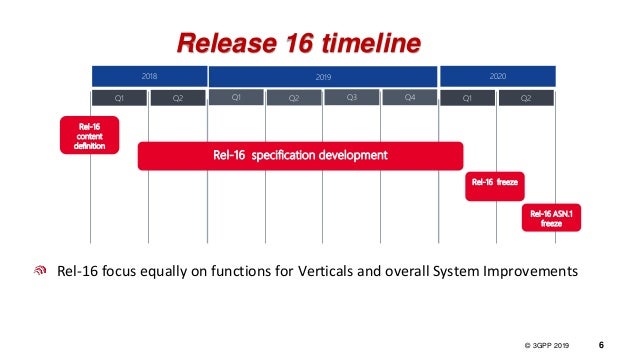
Timelines for IMT 2020 (subject to change) and 3GPP Release 16


15 July 2019 Update & Clarification:
For the completion of Step 8 (see revised description below) and the finalization of the draft new Recommendation ITU-R M.[IMT‑2020.SPECS] in Working Party 5D, a completion date of the WP 5D meeting No. 36, currently planned for 7-14 October 2020 had previously been chosen.
However, this completion date has been shifted to a new WP 5D Meeting #36bis planned for 17-19 November 2020 (shown in above table). The focus of this ‘bis’ meeting is specifically the technology aspects and associated matters necessary to finalize the draft new Recommendation ITU-R M.[IMT-2020.SPECS].
This shift was done to assist the Transposing Organizations by providing them additional time to prepare their transposed standards aligned with the Global Core Specification that would be provided to WP 5D meeting #35 (24 June – 1 July 2020).
The additional time afforded by scheduling a new WP 5D Meeting #36bis as the new completion meeting of the draft new Recommendation ITU-R M.[IMT-2020.SPECS] affords the Transposing Organizations at least 13 weeks of time after WP 5D Meeting #35 to provide the Radiocommunication Bureau by the indicated due date (8 October 2020) with the relevant technical material (e.g., the URL hyperlinks) and other related administrative matters to ITU-R after the Meeting #35, in proper alignment with the GCS.
The ITU-R Secretariat, upon receipt of this material from the Transposing Organizations will administratively prepare (i.e., compile, edit, format, etc.) the final draft of the Recommendation incorporating all the technologies (RITs and SRITs) agreed by ITU-R for inclusion in Step 8 and make it available to WP 5D Meeting #36bis.
Step 8 – Development of radio interface Recommendation(s):
In this step a (set of) IMT-2020 terrestrial component radio interface Recommendation(s) is developed within the ITU-R on the basis of the results of Step 7, sufficiently detailed to enable worldwide compatibility of operation and equipment, including roaming.
This work may proceed in cooperation with relevant organizations external to ITU in order to complement the work within ITU‑R, using the principles set out in Resolution ITU-R 9-5.
Step 9 – Implementation of Recommendation(s):
In this step, activities external to ITU-R include the development of supplementary standards (if appropriate), equipment design and development, testing, field trials, type approval (if appropriate), development of relevant commercial aspects such as roaming agreements, manufacture and deployment of IMT-2020 infrastructure leading to commercial service.
……………………………………………………………………………………………………………………………………………………………………………………………………………
3GPP input to IMT 2020 RIT/SRIT and Release 16 Schedule:
3GPP notes that with the complexities of 5G as a new generation of technology and the importance of the new Recommendation ITU-R M.[IMT-2020.SPECS] globally for all stakeholders (including support for the results of WRC-19), any additional time afforded to the External Organizations in Step 8 for provision of the URL references would be of great benefit to all the radio interface technology proponents, not just 3GPP.
3GPP welcomes any accommodation WP 5D might make concerning the scheduling of the work to conclude the first release of Recommendation ITU-R M.[IMT-2020.SPECS] and kindly asks for feedback to 3GPP from that discussion.
……………………………………………………………………………………………………………………
From 3GPP Webinar – 3 July 2019:
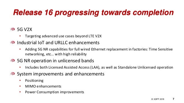
“For the (industry) verticals, there are three distinct pillars that we are focused on: Automotive, Industrial IoT and Operation in unlicensed frequency bands.
For 5G based V2X, which builds on the two iterations of the LTE-V2X, we are now adding advanced features – primarily in the area of low latency use cases.
The second focus is industrial IoT and URLLC enhancements. Factory automation, in particular, is a strong pillar for 5G going forward. We are trying to ensure that the radio side covers all of the functions that all the verticals need for factory automation. What this means in practice is that we are trying to make sure 5G NR can fully replace a wired Ethernet – currently used – by adding time sensitive networking and high reliability capabilities.
The third pillar is operation in unlicensed bands. We have seen different schemes for generic 5G licensing strategies in Europe and in other parts of the World. We have seen in some countries that certain licensed bands have been allocated for vertical use cases, though that is not the case for a majority of countries. The use of unlicensed bands provides a great opportunity – where licensed spectrum is not an option. We are now focused on not only what we have with LTE, which is the licensed assisted access scheme, but also on standalone unlicensed operation – to be completed in Release 16.
Release 16 also delivers generic system improvements & enhancements, which target Mobile Broadband, but can also be used in vertical deployments –> Particularly: positioning, MIMO enhancements and Power consumption improvements.”
See and listen to this 3GPP Webinar at: https://vimeo.com/346171906
………………………………………………………………………………………………………………………………………………….
Annex 1. From ATIS contribution to ITU-R WP5D July 2019 meeting in Brazil:
3GPP has agreed revised completion dates for Release 16 – schedule shifted out by 3 months:
Release 16 RAN-1 Freeze RAN # 86 December 2019
Release 16 RAN Stage 3 Freeze RAN # 87 March 2020
Release 16 ASN.1 Freeze RAN # 88 June 2020
Release 16 RAN-4 Freeze RAN # 89 September 2020
……………………………………………………………………………………………………………………
Submitted on behalf of the 3GPP Proponent of the 3GPP submission, which is collectively the 3GPP Organizational Partners (OPs). The 3GPP OPs are ARIB, ATIS, CCSA, ETSI, TSDSI, TTA and TTC (http://www.3gpp.org/partners)
IMT 2020: Concept of Global Core Specification (GCS) and Transposing Organization(s)
Introduction:
When completed, Recommendation ITU-R M.[IMT-2020.SPECS] will contain the detailed specifications of the radio interfaces of IMT-2020. The structure and philosophy adopted for M.[IMT-2020.SPECS] for IMT2020 is based on those used in Recommendations ITU-R M.1457 for IMT-2000 and ITU-R M.2012 for IMT-Advanced, which have been successfully utilized for two decades through numerous revisions of Recommendations ITU-R M.1457 and ITU-R M.2012.
A key concept is the continued use of the Global Core Specification (GCS) provided by the GCS Proponent and references to standards of Transposing Organization(s) [1.] authorized by the GCS Proponent whereby the detailed standardization is undertaken within the Transposing Organization that operates in concert with the RIT/SRIT Proponent and/or GCS Proponent entities.
The relationship between the GCSs for IMT-2020 radio interface technologies and the corresponding transposed standards is such that the GCSs are the framework for their corresponding detailed transposed specifications. Recommendation ITU-R M.[IMT-2020.SPECS] may also include references to specific related standards of the Transposing Organizations. There may be one or more entities that exist within a GCS Proponent for a given GCS.
It is also permissible to not have a separate GCS for a particular radio interface technology, in which case all the detailed specifications of that particular radio interface technology (the Directly Incorporated Specification1) would be fully contained directly within the Recommendation ITU-R M.[IMT-2020.SPECS].
This understanding of whether a GCS would or would not be utilized in the context of a particular radio interface technology within Recommendation ITU-R M.[IMT-2020.SPECS] is necessary so that the proper structure and content of the Recommendation is chosen to properly reflect the technology specifications.
Consequently, the RIT/SRIT Proponent is requested to indicate at an early stage to the ITU-R its preliminary intention to submit a Global Core Specification, in advance of the required formal certifications, which will be used to form the basis of information in the Recommendation ITU‑R M.[IMT-2020.SPECS].
The ITU-R (Working Party 5D) will review any GCS or DIS submission(s) and agree/approve or suggest changes in conjunction with the development and the ultimate approval by ITU-R of the final published version of Recommendation ITU-R M.[IMT-2020.SPECS] and the established schedules.
ITU-R (WP 5D and/or the Radiocommunication Bureau) will maintain liaison with the relevant External Organizations (RIT/SRIT Proponents, GCS Proponents, and Transposing Organizations) on the required deliverables and also the relevant schedules and administrative matters associated with the various stages of the development of the Recommendation ITU‑R M.[IMT-2020.SPECS] and its revisions over time.
………………………………………………………………………………………………………………………………………..
ITU-R WP 5D will review any GCS or DIS submission(s) and agree/approve or suggest changes in conjunction with the development and the ultimate approval by ITU-R of the final published version of Recommendation ITU-R M.[IMT-2020.SPECS] and the established schedules.
ITU-R (WP 5D and/or the Radiocommunication Bureau) will maintain liaison with the relevant External Organizations (RIT/SRIT Proponents, GCS Proponents, and Transposing Organizations) on the required deliverables and also the relevant schedules and administrative matters associated with the various stages of the development of the Recommendation ITUR M.[IMT-2020.SPECS] and its revisions over time.
Respecting the integrity of the GCSs and ensuring that the transposed standards are consistent with the GCS:
To assure users of Recommendation ITU-R M.[IMT-2020.SPECS] of the integrity of the GCS for a particular technology, and to ensure that the transposed standards are consistent with the common globally agreed vision of IMT-2020, completeness and traceability of the GCS and the transposed standards is a foremost obligation of the ITU-R.
As noted above, the IMT-2020 specifications could be developed around a “Global Core Specification” (GCS), which is related to externally developed materials incorporated by specific references for a specific technology. The submitted GCSs as accepted by WP 5D for inclusion in Recommendation ITU-R M.[IMT-2020.SPECS] will be placed on the relevant ITU website and indicated by hyperlinks in each relevant technology Section of Recommendation ITU-R M.[IMT2020.SPECS].
The GCS provided by the GCS Proponent would form the nucleus of Recommendation ITUR M.[IMT-2020.SPECS]. For each radio interface technology in Recommendation ITU-R M.[IMT2020.SPECS] (whether presented as a single RIT or as one of the component RITs within an SRIT) there will be only one corresponding GCS. A GCS will have one or more GCS Proponents. Each component RIT within a SRIT may be separately addressed with regard to its GCS and the associated GCS Proponents.
Each GCS would correspond to separate sets of transposed standards/specifications from one or more individual standards development organizations or equivalent entities. For each separate set of transposed standards/specifications, there will be only one Transposing Organization.
The referenced standards of the authorized Transposing Organizations [1.] must be technically consistent with the corresponding GCS while allowing a limited amount of flexibility to accommodate, e.g. minimal regional differences. An example of a regional difference would be a regional adjustment for differing frequency bands. Adherence to this format and principle assures a common global standard for IMT-2020 as codified in Recommendation ITU-R M.[IMT2020.SPECS] including the external materials incorporated by reference.
The receipt of information with regard to Recommendation ITUR M.[IMT-2020.SPECS] that is related to a business relationship of the ITU and the relevant external organizations complements and support activities such as the technical work under the purview of the relevant Study Group within the ITU. It must be noted that where this document addresses administrative matters it does not intend to usurp the Study Group or Working Party authority but merely seeks to provide additional critical information to the deliberations on Recommendation ITU-R M.[IMT-2020.SPECS] as to the individual or collective intent and/or actions of the RIT/SRIT Proponents, GCS Proponents, and/or Transposing Organizations that support a particular technology, a corresponding GCS, and the related transposed standards.
NOTE 1. A Transposing Organization is an individual entity authorized by a GCS Proponent to transpose the relevant GCS into specific standards and to provide specific references and hyperlinks (Transposition References) for the purposes of Recommendation ITU-R M.[IMT-2020.SPECS]. A Transposing Organization:
1) must have been authorized by the relevant GCS Proponent to produce transposed standards for a particular technology, and
2) must have the relevant legal usage rights.
………………………………………………………………………………………………………………………………………………………………………….
It is noted that the entity or entities that make up a GCS Proponent may also be a Transposing Organization. It should also be noted that the term Transposing Organization is always indicated to be a single entity. It is also noted that, for the purposes of Recommendation ITU-R M.[IMT-2020.SPECS], the ITUR will only recognize as valid those Transposing Organizations that have been identified to the ITU-R by the GCS Proponent as authorized to transpose the GCS Proponent’s GCS.
Neither a GCS Proponent nor a Transposing Organization need to be a formal “Standards Development Organization” or “SDO.” For example, “SDO” here could represent an industry entity, organization, individual company, etc. that, if applicable, also qualifies appropriately under the auspices of Resolution ITU-R 9.
…………………………………………………………………………………………….
References:
https://www.itu.int/md/R15-IMT.2020-C-0020/en
https://www.itu.int/pub/R-RES-R.9
India’s TSDSI candidate IMT 2020 RIT with Low Mobility Large Cell (LMLC) for rural coverage of 5G services
India’s telecom standards organization TSDSI has submitted its candidate IMT-2020 Radio Interface Technology (RIT) to the IMT-2020 evaluation at the ITU-R WP 5D meeting #32 being held in Buzios, Brazil from 9 July 2019 to 17 July 2019. TSDSI’s IMT 2020 submission is one of five candidate RIT proposals- see NOTE at bottom of this article for more information.
TSDSI’s RIT is described in document ITU-R WP5D-AR Contribution 770. This RIT has been developed to address the rural requirements by enabling the implementation of Low Mobility Large Cell (LMLC), particularly with emphasis on low-cost rural coverage of 5G wireless network services. TSDSI believes that this RIT will also help to meet the rural requirements of other developing countries. This author agrees!
TSDSI proposal on Low Mobility Large Cell (LMLC) configuration has been included as a mandatory test configuration under the Rural eMBB (enhanced Mobile BroadBand) test environment in IMT 2020 Technical Performance Requirements (TPR) in ITU-R with an enhanced Inter Sire Distance (ISD) of 6 km. Incorporation of LMLC in IMT2020 will help address the requirements of typical Indian rural settings and will be a key enabler for bridging the rural-urban divide with 5G rollouts.
–>The Indian administration (ITU member country) extends its support to the RIT of TSDSI and solicits the support of ITU Member States to support this proposal.
Indian wireless network operators, including Reliance Jio Infocomm Ltd, have expressed interest in LMLC.
About TSDSI:
*TSDSI is a Standards development organization similar to ETSI, SRIB, ATIS, CCSA, TTA, TTC, etc.
*TSDSI is an Organisational Partner of 3GPP and oneM2M, an Associate member of ITU-R and ITU-T and a member of GSC.
*TSDSI delegations have been actively participating and contributing in Standards development Working Groups in all these forums.
*TSDSI has formal affiliations (MoUs/Agreements) with – ETSI, 5GIA, ATSC, BIF, CCICI, GCF, IEEE-SA, TIA, TAICs, TTA, WWRF, ARIB, ATIS, CCSA, TTC
*TSDSI conducts several joint activities – projects, workshops, conferences etc. with its affiliates
*TSDSI’s operating procedures have been derived based on best practices being followed by similar Global SDOs.
*TSDSI Rules & Regulations, Working Procedures and IPR Policy are all transparent and available on our website – http://www.tsdsi.in. A brief perusal will show the similarity with the processes and policies followed by other SDOs.
*TSDSI strictly follows the Rules and Procedures. It provides an open, transparent and collaborative platform for its members to participate and contribute in the development of Standards with a special focus on India Specific Requirements and Indian Innovations. The governance model is also very inclusive, open and transparent with fresh elections being conducted for all positions every 2 years.
Submitted by: Chair TSDSI , Vice Chair TSDSI and DG TSDSI
http://www.tsdsi.in
………………………………………………………………………………………………………………………………………….
Kiran Kumar Kuchi, a professor at IIT Hyderabad is building a 5G testbed there. The system will exceed IMT 2020 5G performance requirements including Low Mobility Large Cell.
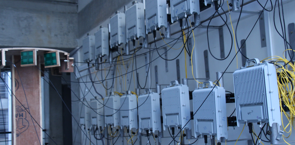
IIT Hyderabad 5G Testbed. Photo courtesy of IIT Hyderabad.
……………………………………………………………………………………………………………………………………………………………………………………………………………
TSDSI’s baseline RIT (initial description template) is documented in ITU-R WP 5D Document 5D/980: Revision 2 to Document IMT-2020/7-E, submitted on 14 February 2019. Several updates to TSDSI RIT included the updated characteristics template, initial link budget template, etc. They are in Document 5D/1138: Attachment Part 1: 5D/1138!P1; Attachment Part 2: 5D/1138!P2; Attachment Part 3: 5D/1138!P3; Attachment Part 4: 5D/1138!P4)
Here are a few key excerpts from the TSDSI baseline RIT:
Describe details of the radio interface architecture and protocol stack such as: – Logical channels – Control channels – Traffic channels Transport channels and/or physical channels.
RAN/Radio Architectures: This RIT contains NR standalone architecture. The following paragraphs provide a high-level summary of radio interface protocols and channels.
Radio Protocols: The protocol stack for the user plane includes the following: SDAP, PDCP, RLC, MAC, and PHY sublayers (terminated in UE and gNB). On the Control plane, the following protocols are defined: – RRC, PDCP, RLC, MAC and PHY sublayers (terminated in UE and gNB); – NAS protocol (terminated in UE and AMF) For details on protocol services and functions, please refer to 3GPP specifications (e.g. [38.300]).
Radio Channels (Physical, Transport and Logical Channels):
- The physical layer offers service to the MAC sublayer transport channels. The MAC sublayer offers service to the RLC sublayer logical channels.
- The RLC sublayer offers service to the PDCP sublayer RLC channels.
- The PDCP sublayer offers service to the SDAP and RRC sublayer radio bearers: data radio bearers (DRB) for user plane data and signalling radio bearers (SRB) for control plane data.
- The SDAP sublayer offers 5GC QoS flows and DRBs mapping function.
The physical channels defined in the downlink are: – the Physical Downlink Shared Channel (PDSCH), – the Physical Downlink Control Channel (PDCCH), – the Physical Broadcast Channel (PBCH).
The physical channels defined in the uplink are: – the Physical Random Access Channel (PRACH), – the Physical Uplink Shared Channel (PUSCH), – and the Physical Uplink Control Channel (PUCCH). In addition to the physical channels above, PHY layer signals are defined, which can be reference signals, primary and secondary synchronization signals.
The following transport channels, and their mapping to PHY channels, are defined:
Uplink: – Uplink Shared Channel (UL-SCH), mapped to PUSCH – Random Access Channel (RACH), mapped to PRACH
Downlink: – Downlink Shared Channel (DL-SCH), mapped to PDSCH – Broadcast channel (BCH), mapped to PBCH – Paging channel (PCH), mapped to (TBD)
Logical channels are classified into two groups: Control Channels and Traffic Channels.
Control channels: – Broadcast Control Channel (BCCH): a downlink channel for broadcasting system control information. – Paging Control Channel (PCCH): a downlink channel that transfers paging information and system information change notifications. – Common Control Channel (CCCH): channel for transmitting control information between UEs and network. – Dedicated Control Channel (DCCH): a point-to-point bi-directional channel that transmits dedicated control information between a UE and the network.
Traffic channels: Dedicated Traffic Channel (DTCH), which can exist in both UL and DL. In Downlink, the following connections between logical channels and transport channels exist: – BCCH can be mapped to BCH, or DL-SCH; – PCCH can be mapped to PCH; – CCCH, DCCH, DTCH can be mapped to DL-SCH;
In Uplink, the following connections between logical channels and transport channels exist: – CCCH, DCCH, DTCH can be mapped to UL-SCH.
Enhancements:
1. Method to improve broadcast and paging control channel efficiency over access elements.
2. Reduce the impact of congestion in the data path and control path to improve overall efficiency in the network.
3. Other aspects
– NR QoS architecture The QoS architecture in NG-RAN (connected to 5GC), can be summarized as follows: For each UE, 5GC establishes one or more PDU Sessions. For each UE, the NG-RAN establishes one or more Data Radio Bearers (DRB) per PDU Session. The NG-RAN maps packets belonging to different PDU sessions to different DRBs. Hence, the NG-RAN establishes at least one default DRB for each PDU Session. NAS level packet filters in the UE and in the 5GC associate UL and DL packets with QoS Flows. AS-level mapping rules in the UE and in the NG-RAN associate UL and DL QoS Flows with DRBs
– Carrier Aggregation (CA) In case of CA, the multi-carrier nature of the physical layer is only exposed to the MAC layer for which one HARQ entity is required per serving cell.
– Dual Connectivity (DC) In DC, the radio protocol architecture that a radio bearer uses depends on how the radio bearer is setup.
…………………………………………………………………………………………………………..
Four bearer types (information carrying channels) exist: MCG bearer, MCG split bearer, SCG bearer and SCG split bearer.
The following terminology/definitions apply:
– Master gNB: in dual connectivity, the gNB which terminates at least NG-C.
– Secondary gNB: in dual connectivity, the gNB that is providing additional radio resources for the UE but is not the Master node.
– Master Cell Group (MCG): in dual connectivity, a group of serving cells associated with the MgNB
– Secondary Cell Group (SCG): in dual connectivity, a group of serving cells associated with the SgNB
– MCG bearer: in dual connectivity, a bearer whose radio protocols are only located in the MCG.
– MCG split bearer: in dual connectivity, a bearer whose radio protocols are split at the MgNB and belong to both MCG and SCG.
– SCG bearer: in dual connectivity, a bearer whose radio protocols are only located in the SCG.
– SCG split bearer: in dual connectivity, a bearer whose radio protocols are split at the SgNB and belong to both SCG and MCG.
In case of DC, the UE is configured with two MAC entities: one MAC entity for the MCG and one MAC entity for the SCG. For a split bearer, UE is configured over which link (or both) the UE transmits UL PDCP PDUs. On the link which is not responsible for UL PDCP PDUs transmission, the RLC layer only transmits corresponding ARQ feedback for the downlink data.
What is the bit rate required for transmitting feedback information? The information will be provided in later update.
……………………………………………………………………………………………………………………
LMLC Detailed Description – Characteristics template for TSDSI RIT:
The description template provides the characteristics description of the TSDSI RIT.
For this characteristic template, it has chosen to address the characteristics that are viewed to be very crucial to assist in evaluation activities for independent evaluation groups, as well as to facilitate the understanding of the RIT.
Channel access: Describe in detail how RIT/SRIT accomplishes initial channel access, (e.g. contention or non-contention based).
Initial channel access is typically accomplished via the “random access procedure” (assuming no dedicated/scheduled resources are allocated). The random access procedure can be contention based (e.g. at initial connection from idle mode) or non-contention based (e.g. during Handover to a new cell). Random access resources and parameters are configured by the network and signaled to the UE (via broadcast or dedicated signaling). Contention based random access procedure encompasses the transmission of a random access preamble by the UE (subject to possible contention with other UEs), followed by a random access response (RAR) in DL (including allocating specific radio resources for the uplink transmission). Afterwards, the UE transmits the initial UL message (e.g. RRC connection Request) using the allocated resources, and wait for a contention resolution message in DL (to confirming access to that UE). The UE could perform multiple attempts until it is successful in accessing the channel or until a timer (supervising the procedure) elapses. Non-contention based random access procedure foresees the assignment of a dedicated random access resource/preamble to a UE (e.g. part of an HO command). This avoids the contention resolution phase, i.e. only the random access preamble and random access response messages are needed to get channel access.
From a PHY perspective, a random access preamble is transmitted (UL) in a PRACH, random access response (DL) in a PDSCH, UL transmission in a PUSCH, and contention resolution message (DL) in a PDSCH.
……………………………………………………………………………………………………………………
| Radio interface functional aspects: | ||||||||||||||||||
| Multiple access schemes
Which access scheme(s) does the proposal use? Describe in detail the multiple access schemes employed with their main parameters. – Downlink and Uplink: The multiple access is a combination of ● OFDMA: Synchronous/scheduling-based; the transmission to/from different UEs uses mutually orthogonal frequency assignments. Granularity in frequency assignment: One resource block consisting of 12 subcarriers. Multiple sub-carrier spacings are supported including 15kHz, 30kHz, 60kHz and 120kHz for data (see Item 5.2.3.2.7 and reference therein). 1. CP-OFDM is applied for downlink. DFT-spread OFDM and CP-OFDM are available for uplink. 2. Spectral confinement technique(s) (e.g. filtering, windowing, etc.) for a waveform at the transmitter is transparent to the receiver. When such confinement techniques are used, the spectral utilization ratio can be enhanced. ● TDMA: Transmission to/from different UEs with separation in time. Granularity: One slot consists of 14 OFDM symbols and the physical length of one slot ranges from 0.125ms to 1ms depending on the sub-carrier spacing (for more details on the frame structure, see Item 5.2.3.2.7 and the references therein). ● SDMA: Possibility to transmit to/from multiple users using the same time/frequency resource (SDMA a.k.a. “multi-user MIMO”) as part of the advanced-antenna capabilities (for more details on the advanced-antenna capabilities, see Item 5.2.3.2.9 and the reference therein) At least an UL transmission scheme without scheduling grant is supported for initial access. Inter-cell interference suppressed by processing gain of channel coding allowing for a frequency reuse of one (for more details on channel-coding, see Item 5.2.3.2.2.3 and the reference therein). (Note: Synchronous means that timing offset between UEs is within cyclic prefix by e.g. timing alignment.) For NB-IoT, the multiple access is a combination of OFDMA, TDMA, where OFDMA and TDMA are as follows · OFDMA: n UL: DFT-spread OFDM. Granularity in frequency domain: A single sub-carrier with either 3.75 kHz or 15 kHz sub-carrier spacing, or 3, 6, or 12 sub-carriers with a sub-carrier spacing of 15 kHz. A resource block consists of 12 sub-carriers with 15 kHz sub-carrier spacing, or 48 sub-carriers with 3.75 kHz sub-carrier spacing → 180 kHz. n DL: Granularity in frequency domain: one resource block consisting of 6 or 12 subcarriers with 15 kHz sub-carrier spacing→90 or 180 kHz · TDMA: Transmission to/from different UEs with separation in time n UL: Granularity: One resource unit of 1 ms, 2 ms, 4 ms, 8 ms, with 15 kHz sub-carrier spacing, depending on allocated number of sub-carrier(s); or 32 ms with 3.75 kHz sub-carrier spacing (for more details on the frame structure, see Item 5.2.3.2.7 and the references therein) n DL: Granularity: One resource unit (subframe) of length 1 ms. Repetition of a transmission is supported |
||||||||||||||||||
| Modulation scheme | ||||||||||||||||||
| What is the baseband modulation scheme? If both data modulation and spreading modulation are required, describe in detail.
Describe the modulation scheme employed for data and control information. What is the symbol rate after modulation? – Downlink: ● For both data and higher-layer control information: QPSK, 16QAM, 64QAM and 256QAM (see [T3.9038.211] sub-clause 7.3.1.2). ● L1/L2 control: QPSK (see [T3.9038.211] sub-clause 7.3.2.4). ● Symbol rate: 1344ksymbols/s per 1440kHz resource block (equivalently 168ksymbols/s per 180kHz resource block) – Uplink: ● For both data and higher-layer control information: π/2-BPSK with spectrum shaping, QPSK, 16QAM, 64QAM and 256QAM (see [T3.9038.211] sub-clause 6.3.1.2). ● L1/L2 control: BPSK, π/2-BPSK with spectrum shaping, QPSK (see [T3.9038.211] sub-clause 6.3.2). ● Symbol rate: 1344ksymbols/s per 1440kHz resource block (equivalently 168ksymbols/s per 180kHz resource block) The above is at least applied to eMBB. For NB-IoT, the modulation scheme is as follows. · Data and higher-layer control: π/2-BPSK (uplink only), π/4-QPSK (uplink only), QPSK · L1/L2 control: π/2-BPSK (uplink), QPSK (uplink), QPSK (downlink) Symbol rate: 168 ksymbols/s per 180 kHz resource block. For UL, less than one resource block may be allocated. |
||||||||||||||||||
| PAPR
What is the RF peak to average power ratio after baseband filtering (dB)? Describe the PAPR (peak-to-average power ratio) reduction algorithms if they are used in the proposed RIT/SRIT. The PAPR depends on the waveform and the number of component carriers. The single component carrier transmission is assumed herein when providing the PAPR. For DFT-spread OFDM, PAPR would depend on modulation scheme as well. For uplink using DFT-spread OFDM, the cubic metric (CM) can also be used as one of the methods of predicting the power de-rating from signal modulation characteristics, if needed. – Downlink: The PAPR is 8.4dB (99.9%) – Uplink: ● For CP-OFDM: The PAPR is 8.4dB (99.9%) ● For DFT-spread OFDM: The PAPR is provided in the table below.
Any PAPR-reduction algorithm is transmitter-implementation specific for uplink and downlink. For NB-IoT, – Downlink: The PAPR is 8.0dB (99.9%) on 180kHz resource. – Uplink: The PAPR is 0.23 – 5.6 dB (99.9 %) depending on sub-carriers allocated for available NB-IoT UL modulation. |
||||||||||||||||||
| Error control coding scheme and interleaving | ||||||||||||||||||
| Provide details of error control coding scheme for both downlink and uplink.
For example, – FEC or other schemes? The proponents can provide additional information on the decoding schemes. – Downlink and Uplink: ● For data: Rate 1/3 or 1/5 Low density parity check (LDPC) coding, combined with rate matching based on puncturing/repetition to achieve a desired overall code rate (For more details, see [T3.9038.212] sub-clauses 5.3.2). LDPC channel coder facilitates low-latency and high-throughput decoder implementations. ● For L1/L2 control: For DCI (Downlink Control Information)/UCI (Uplink Control Information) size larger than 11 bits, Polar coding, combined with rate matching based on puncturing/repetition to achieve a desired overall code rate (For more details, see [T3.9038.212] sub-clauses 5.3.1). Otherwise, repetition for 1-bit; simplex coding for 2-bit; reedmuller coding for 3~11-bit DCI/UCI size. The above scheme is at least applied to eMBB. Decoding mechanism is receiver-implementation specific For NB-IoT, the coding scheme is as follows: · For data: Rate 1/3 Turbo coding in UL, and rate-1/3 tail-biting convolutional coding in DL, each combined with rate matching based on puncturing/repetition to achieve a desired overall code rate; one transport block can be mapped to one or multiple resource units (for more details, see [T3.9036.212] sub-clause 6.2) · For L1/L2 control: For L1/L2 control: Rate-1/3 tail-biting convolutional coding. Special block codes for some L1/L2 control signaling (For more details, see [T3.9036.212] sub-clauses 5.1.3.1) |
||||||||||||||||||
| Describe the bit interleaving scheme for both uplink and downlink.
– Downlink: ● For data: bit interleaver is performed for LDPC coding after rate-matching (For more details, see [T3.9038.212] sub-clauses 5.4.2.2) ● For L1/L2 control: Bit interleaving is performed as part of the encoding process for Polar coding (For more details, see [T3.9038.212] sub-clauses 5.4.1.1) – Uplink: ● For data: bit interleaver is performed for LDPC coding after rate-matching (For more details, see [T3.9038.212] sub-clauses 5.4.2.2) ● For L1/L2 control: Bit interleaving is performed for Polar coding after rate-matching (For more details, see [T3.9038.212] sub-clauses 5.4.1.3) The above scheme is at least applied to eMBB. NB-IOT Uplink For Control (Format 2) : Bit interleaver is not applied For Data (Format1): Bit interleaver is performed after rate matching only for multitone transmissions (3,6,12). For single tone transmissions it is not applicable. -Downlink Bit interleaver is not applied
|
||||||||||||||||||
| Describe channel tracking capabilities (e.g. channel tracking algorithm, pilot symbol configuration, etc.) to accommodate rapidly changing delay spread profile.
To support channel tracking, different types of reference signals can be transmitted on downlink and uplink respectively. – Downlink: ● Primary and Secondary Synchronization signals (PSS and SSS) are transmitted periodically to the cell. The periodicity of these signals is network configurable. UEs can detect and maintain the cell timing based on these signals. If the gNB implements hybrid beamforming, then the PSS and SSS are transmitted separately to each analogue beam. Network can configure multiple PSS and SSS in frequency domain. ● UE-specific Demodulation RS (DM-RS) for PDCCH can be used for downlink channel estimation for coherent demodulation of PDCCH (Physical Downlink Control Channel). DM-RS for PDCCH is transmitted together with the PDCCH. ● UE-specific Demodulation RS (DM-RS) for PDSCH can be used for downlink channel estimation for coherent demodulation of PDSCH (Physical Downlink Shared Channel). DM-RS for PDSCH is transmitted together with the PDSCH. ● UE-specific Phase Tracking RS (PT-RS) can be used in addition to the DM-RS for PDSCH for correcting common phase error between PDSCH symbols not containing DM-RS. It may also be used for Doppler and time varying channel tracking. PT-RS for PDSCH is transmitted together with the PDSCH upon need. ● UE-specific Channel State Information RS (CSI-RS) can be used for estimation of channel-state information (CSI) to further prepare feedback reporting to gNB to assist in MCS selection, beamforming, MIMO rank selection and resource allocation. CSI-RS transmissions are transmitted periodically, aperiodically, and semi-persistently on a configurable rate by the gNB. CSI-RS also can be used for interference measurement and fine frequency/time tracking purposes. – Uplink: ● UE-specific Demodulation RS (DM-RS) for PUCCH can be used for uplink channel estimation for coherent demodulation of PUCCH (Physical Uplink Control Channel). DM-RS for PUCCH is transmitted together with the PUCCH. ● UE-specific Demodulation RS (DM-RS) for PUSCH can be used for uplink channel estimation for coherent demodulation of PUSCH (Physical Uplink Shared Channel). DM-RS for PUSCH is transmitted together with the PUSCH. ● UE-specific Phase Tracking RS (PT-RS) can be used in addition to the DM-RS for PUSCH for correcting common phase error between PUSCH symbols not containing DM-RS. It may also be used for Doppler and time varying channel tracking. DM-RS for PUSCH is transmitted together with the PUSCH upon need. ● UE-specific Sounding RS (SRS) can be used for estimation of uplink channel-state information to assist uplink scheduling, uplink power control, as well as assist the downlink transmission (e.g. the downlink beamforming in the scenario with UL/DL reciprocity). SRS transmissions are transmitted periodically aperiodically, and semi-persistently by the UE on a gNB configurable rate. Details of channel-tracking/estimation algorithms are receiver-implementation specific, and not part of the specification. Details of channel-tracking/estimation algorithms are receiver-implementation specific, e.g. MMSE-based channel estimation with appropriate interpolation in time and frequency domain could be used. NB-IOT NB-IoT is based on following signals transmitted in the downlink: the primary and secondary narrowband synchronization signals. The narrowband primary synchronization sequence is transmitted over 11 sub-carriers from the first subcarrier to the eleventh subcarrier in the sixth subframe of each frame, and the narrowband secondary synchronization sequence is transmitted over 12 sub-carriers in the NB-IoT carrier in the tenth subframe of every other frame. ● Demodulation RS (DM-RS) for NPUSCH format 1&2 (used for Data and control respectively) can be used for uplink channel estimation for coherent demodulation of NPUSCH F1 & F2 (Narrowband Physical Uplink Shared Channel Format 1 and 2). DM-RS for NPUSCH F1& F2 is transmitted together with the NPUSCH F1 & F2. They are not UE specific, as they do not depend on RNTI. The reference sequence generation is different for single tone and multi tone. For more details refer to [T3.9036.211] For single-tone NPUSCH with UL-SCH demodulation, uplink demodulation reference signals are transmitted in the 4- th block of the slot for 15 kHz subcarrier spacing, and in the 5-th block of the slot for 3.75 kHz subcarrier spacing. For multi-tone NPUSCH with UL-SCH demodulation, uplink demodulation reference signals are transmitted in the 4-th block of the slot. The uplink demodulation reference signals sequence length is 16 for single-tone NPUSCH with ULSCH transmission, and equals the size (number of sub-carriers) of the assigned resource for multi-tone transmission. For single-tone NPUSCH with UL-SCH transmission, multiple narrow band reference signals can be created: – Based on different base sequences; – A common Gold sequence. For multi-tone NPUSCH with UL-SCH transmission, multiple narrow band reference signals are created: – Based on different base sequences; – Different cyclic shifts of the same sequence. For NPUSCH with ACK/NAK demodulation, uplink demodulation reference signals are transmitted in the 3-rd, 4-th and 5-th block of the slot for 15 kHz subcarrier spacing, and in the 1-st, 2-nd and 3-rd block of the slot for 3.75 kHz subcarrier spacing. Multiple narrow band reference signals can be created: – Based on different base sequences; – A common Gold sequence; – Different orthogonal sequences (OCC). |
||||||||||||||||||
| Physical channel structure and multiplexing | ||||||||||||||||||
| What is the physical channel bit rate (M or Gbit/s) for supported bandwidths?
i.e., the product of the modulation symbol rate (in symbols per second), bits per modulation symbol, and the number of streams supported by the antenna system. The physical channel bit rate depends on the modulation scheme, number of spatial-multiplexing layer, number of resource blocks in the channel bandwidth and the subcarrier spacing used. The physical channel bit rate per layer can be expressed as Rlayer = Nmod x NRB x 2µ x 168 kbps where – Nmod is the number of bits per modulation symbol for the applied modulation scheme (QPSK: 2, 16QAM: 4, 64QAM: 6, 256QAM: 8) – NRB is the number of resource blocks in the aggregated frequency domain which depends on the channel bandwidth. – µ depends on the subcarrier spacing, , given by For example, a 400 MHz carrier with 264 resource blocks using 120 kHz subcarrier spacing, , and 256QAM modulation results in a physical channel bit rate of 2.8 Gbit/s per layer. NB-IOT The physical channel bit rate depends on the modulation scheme, number of tones used in the channel bandwidth in the resource block and the subcarrier spacing used. The physical channel bit rate per user can be expressed as : Uplink NPUSCH Format 1 R = Nmod x Ntone x 12 kbps for carrier spacing of 15kHz where – Nmod is the number of bits per modulation symbol for the applied modulation scheme (QPSK: 2, BPSK:1) – Ntone is the number of tones . This can be 1,3,6,12 R = Nmod x 3 kbps for carrier spacing of 3.75kHz Downlink R = Nmod x 12 x 12 kbps |
||||||||||||||||||
| Layer 1 and Layer 2 overhead estimation.
Describe how the RIT/SRIT accounts for all layer 1 (PHY) and layer 2 (MAC) overhead and provide an accurate estimate that includes static and dynamic overheads. – Downlink The downlink L1/L2 overhead includes: 1. Different types of reference signals a. Demodulation reference signals for PDSCH (DMRS-PDSCH) b. Phase-tracking reference signals for PDSCH (PTRS-PDSCH) c. Demodulation reference signals for PDCCH d. Reference signals specifically targeting estimation of channel-state information (CSI-RS) e. Tracking reference signals (TRS) 2. L1/L2 control signalling transmitted on the up to three first OFDM symbols of each slot 3. Synchronization signals and physical broadcast control channel including demodulation reference signals included in the SS/PBCH block 4. PDU headers in L2 sub-layers (MAC/RLC/PDCP) The overhead due to different type of reference signals is given in the table below. Note that demodulation reference signals for PDCCH is included in the PDCCH overhead.
The overhead due to the L1/L2 control signalling is depending on the size and periodicity of the configured CORESET in the cell and includes the overhead from the PDCCH demodulation reference signals. If the CORESET is transmitted in every slot, maximum control channel overhead is 21% assuming three symbols and whole carrier bandwidth used for CORESET, while a more typical overhead is 7% when 1/3 of the time and frequency resources in the first three symbols of a slot is allocated to PDCCH. The overhead due to the SS/PBCH block is given by the number of SS/PBCH blocks transmitted within the SS/PBCH block period, the SS/PBCH block periodicity and the subcarrier spacing. Assuming a 100 resource block wide carrier, the overhead for 20 ms periodicity is in the range of 0.6 % to 2.3 % if the maximum number of SS/PBCH blocks are transmitted. – Uplink L1/L2 overhead includes: 1. Different types of reference signals a. Demodulation reference signal for PUSCH b. Demodulation reference signal for PUCCH c. Phase-tracking reference signals a. Sounding reference signal (SRS) used for uplink channel-state estimation at the network side 2. L1/L2 control signalling transmitted on a configurable amount of resources (see also Item 4.2.3.2.4.5) 3. L2 control overhead due to e.g., random access, uplink time-alignment control, power headroom reports and buffer-status reports 4. PDU headers in L2 layers (MAC/RLC/PDCP) The overhead due to due to demodulation reference signal for PUSCH is the same as the overhead for demodulation reference signal for PDSCH, i.e. 4 % to 29 % depending on number of symbols configured. Also, the phase-tracking reference signal overhead is the same in UL as in DL. The overhead due to periodic SRS is depending on the number of symbols configured subcarrier spacing and periodicity. For 20 ms periodicity, the overhead is in the range of 0.4% to 1.4% assuming15 kHz subcarrier spacing. Amount of uplink resources reserved for random access depends on the configuration. The relative overhead due to uplink time-alignment control depends on the configuration and the number of active UEs within a cell. The amount of overhead for buffer status reports depends on the configuration. The amount of overhead caused by 4 highly depends on the data packet size. ……………………………………………………………………………………………………………….. For NB-IoT, the overhead from Narrowband RS (NRS) is dependent on the number of cell-specific antenna ports N (1 or 2) and equals 8 x N / 168 %. The overhead from NB-IoT downlink control signaling is dependent on the amount of data to be transmitted. For small infrequent data transmissions, the downlink transmissions are dominated by the L2 signaling during the connection setup. The overhead from L1 signaling is dependent on the configured scheduling cycle. The overhead due to Narrowband synchronization signal and Narrowband system information broadcast messages is only applicable to the NB-IoT anchor carrier. The actual overhead depends on the broadcasted system information messages and their periodicity. The overhead can be estimated to be around 26.25%.
For NB-IoT UL, data and control are sharing the same resources and the overhead from L1/L2 control signaling depend on the scheduled traffic in the DL. The UL control signaling is dominated by RLC and HARQ positive or negative acknowledgments. A typical NB-IoT NPRACH overhead is in the order of 5 %. |
||||||||||||||||||
| Variable bit rate capabilities:
Describe how the proposal supports different applications and services with various bit rate requirements. For a given combination of modulation scheme, code rate, and number of spatial-multiplexing layers, the data rate available to a user can be controlled by the scheduler by assigning different number of resource blocks for the transmission. In case of multiple services, the available/assigned resource, and thus the available data rate, is shared between the services. |
||||||||||||||||||
| Variable payload capabilities:
Describe how the RIT/SRIT supports IP-based application layer protocols/services (e.g., VoIP, video-streaming, interactive gaming, etc.) with variable-size payloads. See also 5.2.3.2.4.3.
The transport-block size can vary between X bits and Y bits. The number of bits per transport block can be set with a fine granularity. See [T3.9038.214] sub-clause 5.1.3.2 for details.
For NB-IoT, the maximum transport block size is 680 bits in the DL and 1000 bits in UL for the lowest UE category and 2536 bits for both DL and UL for the highest UE category. See [T3.9036.213] sub-clause 16.4.1.5.1 for details. |
||||||||||||||||||
| Signalling transmission scheme:
Describe how transmission schemes are different for signalling/control from that of user data. – Downlink L1/L2 control signalling is transmitted in assigned resources time and frequency multiplexed with data within the bandwidth part (BWP, see item 5.2.3.2.8.1). Control signalling is limited to QPSK modulation (QPSK, 16QAM, 64QAM and 256QAM for data). Control signalling error correcting codes are polar codes (LDPC codes for data). – Uplink L1/L2 control signalling transmitted in assigned resources and can be time and frequency multiplexed with data within the BWP. L1/L2 control signalling can also be multiplexed with data on the PUSCH. Modulation schemes for L1/L2 control signalling is π/2-BPSK, BPSK and QPSK. Control signalling error correcting codes are block codes for small payload and polar codes for larger payloads (LDPC codes for data).
For both downlink and uplink, higher-layer signalling (e.g. MAC, RLC, PDCP headers and RRC signalling) is carried within transport blocks and thus transmitted using the same physical-layer transmitter processing as user data.
For NB-IoT the L1/L2 control signaling is confined to a configured set of resource blocks and can be time multiplexed with data and are transmitted in scheduled subframes |
||||||||||||||||||
| Small signalling overhead
Signalling overhead refers to the radio resource that is required by the signalling divided by the total radio resource which is used to complete a transmission of a packet. The signalling includes necessary messages exchanged in DL and UL directions during a signalling mechanism, and Layer 2 protocol header for the data packet. Describe how the RIT/SRIT supports efficient mechanism to provide small signalling overhead in case of small packet transmissions. There are multiple control channel formats that have included, and provide various levels of overhead. There is an overhead versus scheduling flexibility trade-off that can be used by the scheduler to reduce the signalling overhead.
NB-IOT: In case of small data packet transmission, the L1/L2 control signalling during the connection setup procedure is dominating the uplink and downlink transmissions. To minimize this overhead NB-IoT, allows a UE to resume of an earlier connection. As an alternative, the data can be transmitted over the control plane, which eliminates the need to setup the data plane connection. |
NOTES:
1. TSDSI’s RIT is one of five proposals for the IMT 2020 RIT/SRIT.
The other four are from: 3GPP, South Korea, China, and ETSI/DECT Forum. All but the latter are based on 3GPP “5G NR.”
- The Candidate RIT/SRIT submission from China, as acknowledged in IMT-2020/5, is technically identical to the 5G NR RIT submitted from 3GPP as acknowledged in IMT-2020/3.
- The candidate RIT/SRIT submission from South Korea, as acknowledged in IMT-2020/4, is technically identical to the 5G NR RIT submitted from 3GPP as acknowledged in IMT-2020/3.
……………………………………………………………………………………………………………………………………………………………………………………………………………
2. 3GPP release 16:
As we have stated numerous times, 3GPP’s final IMT 2020 RIT/SRIT submission to ITU-R WP 5D will be largely based on 3GPP release 16 (with perhaps some elements of release 15 also included). From the 3GPP website:
Release 16 will meet the ITU IMT-2020 submission requirements and the time-plan as outlined in RP-172101.
Some Background on 3GPP Release 16:
- Early progress on Rel-16 bands for 5G
- “Working towards full 5G in Rel-16″…See a webinar presentation (Bright talk webinar)
- Preparing the ground for IMT-2020
- SA1 completes its study into 5G requirements
Here is the active status of 3GPP release 16 project.
The 3GPP release 16 completion date has been delayed by at least 3 months (1Q 2020) with no new completion date specified at this time.
3. DECT Forum/ETSI submission for IMT 2020 SRIT:
From a July 1, 2019 contribution to ITU-R WP5D Brazil meeting:
DECT Forum would like to announce its support and endorsement for the IMT-2020 contribution from ETSI for an SRIT candidate for inclusion in IMT-2020. The proposed SRIT consists of two component RITs:
⦁ DECT-2020 NR RIT
⦁ 3GPP 5G CANDIDATE FOR INCLUSION IN IMT-2020: SUBMISSION 2 FOR IMT-2020 (RIT)
DECT Forum confirms its continuation as a proponent of this IMT-2020 proposal.
……………………………………………………………………………………………………………………………………………………………………………………………………………
References:
India delays 5G trials; Advocates “the Indian Way” within ITU-R WP 5D for IMT 2020
3GPP Workshop: IMT 2020 Submission to ITU-R WP5D and Timelines for 5G Standards Completion
ITU-R Proposal: Report on IMT-2020 for remote sparsely populated areas providing high data rate coverage
Proposal to develop a draft new ITU-R WP 5D Report on IMT-2020 for remote sparsely populated areas providing high data rate coverage
ITU-R WP5D July 2019 meeting contribution by LM Ericsson
Abstract:
Ericsson proposes that ITU-R WP 5D develops a Report that addresses the specific needs for high data rate coverage for sparsely populated and under-served areas using suitable frequency spectrum bands.
[This author thoroughly agrees with Ericsson’s proposal!]
Introduction:
IMT-2020 networks have the capacity of satisfying the need for high data rate coverage for enhanced mobile broadband services in under-served and remote, sparsely populated areas. In this contribution we are suggesting that work be started on a Report giving details on prospects associated with the provisioning of enhanced mobile broadband services to remote, sparsely populated and underserved areas, proposing enhancements of user equipment (UE) as well as for networks in suitable frequency bands
- for user equipment, possible solutions based on affordable user deployed equipment combined with access to local spectrum at user premises could be considered and examined, and
- for network equipment, possible solutions based on high gain massive MIMO antennas could be reviewed.
A significant part of the global population is currently connected to existing cellular and mobile broadband sites. As a complement, users in remote sparsely populated and under-served areas could be connected to higher tower sites.
The proposed Report could, for example, consider an existing GSM cellular site grid designed for voice coverage, which could be estimated to reach high downlink data rates at a cell edge of IMT-2020 coverage ranges using conventional UE and network equipment. The Report would need, however, to focus on and consider the uplink performance characteristics which may be regarded as not being satisfactory without further elaborations on policy, spectrum and other aspects. For example, consider suggesting enhancements on UE and network equipment as well as consider using high tower installations that may provide coverage reach far beyond that is currently supported by typical GSM sites.
Background:
With regard to current perceptions, it is easy to get the impression that IMT-2020 is primarily targeting a shorter-range network build using millimeter wave (mmW) bands supporting extremely demanding requirements on latency, capacity, and very high peak data rates.
However, it is suggested that IMT-2020 is designed to operate in frequency bands ranging from low-bands to high-bands and can be configured to perform better or on-par with IMT-Advanced in every aspect, also in rural sparsely populated areas. IMT-2020 has evolved from IMT-Advanced, adding significant improvements to an already capable and proven design. IMT-2020 provides two fundamental benefits relevant for longer-range coverage
- Firstly, it is designed to fully utilize massive MIMO, and
- Secondly, it is based on a flexible and lean design reducing energy consumption.
To achieve longer-range, earlier cellular and mobile broadband systems have relied on low-bands. System operated in bands around the frequency range 450 MHz having excellent coverage, but with the limitation of available bandwidth. Pushing uses to higher and higher frequency bands is clearly resulting in increased capacity, but also in reduced coverage range.
For IMT-2020 massive MIMO configuration there is no longer a simple relation between low-band use and longer-range coverage. Using high-band frequencies the size of individual antenna element decreases, resulting in reduced efficiency of each antenna element. However, with massive MIMO this effect can be compensated for by adding antenna elements, effectively keeping the physical antenna size constant while moving to higher frequency bands.
Long-range cellular coverage is very much about using higher towers, higher power, and high gain antennas. In previous cellular systems, higher radio frequency (RF) power resulted in larger network energy consumption. IMT-2020 efficiently supports lean-design and massive MIMO as it provides the right tools to deploy longer-range systems supporting high peak data rates with lower average network energy consumption.
One offered solution to achieve both good coverage as well as high capacity is to use two or more frequency bands from low-band, mid-band and / or high-band, in an aggregated configuration. This approach has proven to be very effective in dense urban areas when deploying IMT-2020 in mmW bands in combination with a low-band or mid-band that can provide improved coverage.
When combined in an effective way, the high-band off-loads the traffic from the low-band and / or mid-band, resulting in significantly improved coverage as well as capacity. This could potentially also be a promising solution for bringing IMT-2020 to underserved rural sparsely populated areas. Combining IMT-2020 using a band in the range 3.5 GHz and IMT-Advanced in a band below the frequency 1 GHz on a GSM cellular grid can provide superior capacity compared to a standalone IMT-Advanced network deployment below 1 GHz. The reason being that in mid-bands in the range 3.5 GHz there is access to more bandwidth, and the low-band on a band below 1 GHz, provide coverage for cell edge users at the same time.
Considering the above, the proposed Report could review, discuss and assess the feasibility for potential enhancements for both network equipment and UE, it may consequently be viable to deploy IMT-2020 network in a band in the range 3.5 GHz providing high capacity and long-range coverage in underserved rural sparsely populated areas. This could be more feasible and economical than deploying new sites in these areas.
IMT-2020 could potentially provide high peak data rate and high capacity mobile broadband services in underserved rural sparsely populated areas by utilizing a band in the range 3.5 GHz, where typically 100 MHz bandwidth is available compared to 20 MHz that can be expected to be available in band in the range below 1 GHz. The Report could elaborate several possible enhancements using higher towers for extended range coverage. Further contribution based on studies, within the context of the proposed Report, would be required to find a technically as well as economically best practice solution resulting in sufficiently long-range, cell-edge throughput, and capacity. Such a solution could be to consider and review the use of both the existing grid of cellular towers and possibly the higher but also sparser television towers in combination, as well as reviewing a standalone 3.5 GHz configuration, or possible aggregation between the range 3.5 GHz for downlink and low-bands for uplink.
In addition, spectrum and policy aspects having a possible impact on a feasible network configuration may need to be addressed by a possible Report.
Proposals:
Ericsson proposes that WP 5D develops a draft new Report that addresses the specific needs for high data rate coverage for sparsely populated and under-served areas using suitable frequency spectrum.
Editor’s Note:
Attachments 1 and 2 of Ericcson’s proposal, with more detailed proposals and time schedules, are only available to ITU member organizations and individuals with a TIES account.
FCC’s auction of 24 GHz spectrum attracts >$1.5B in bids after 26 rounds; IMT 2020 frequencies?
Bids in the Federal Communications Commission’s (FCC’s) 24 GHz millimeter-wave spectrum auction 102 have passed $1.5 billion after 26 rounds. The figure is more than double the the $704 million collected during the recent sale of 28 GHz spectrum.
Bidding has been from AT&T, T-Mobile US, Verizon and Sprint (bidding as ATI Sub LLC); U.S. Cellular; Dish Network, bidding as Crestone Wireless; Starry Spectrum Holdings and Windstream Communications (which recently filed for bankruptcy protection in the wake of a court case). There are a total of 38 qualified bidders.
Auction 102 is the FCC’s second auction of Upper Microwave Flexible Use Service (UMFUS) licenses (see below for information on auction 1010). Auction 102 offers 2,909 licenses in the 24 GHz band. The lower segment of the 24 GHz band (24.25–24.45 GHz) will be licensed as two 100-megahertz blocks, and the upper segment (24.75–25.25 GHz) will be licensed as five 100-megahertz blocks. Those frequencies are being considered for the IMT 2020 5G radio aspects standard and will be determined at the ITU-R WRC-19 meeting this fall (details in Editor’s Note below).

Three rounds of bidding are being held each day at this point in the auction. The clock auction format begins with a “clock phase” (the current auction phase) which lets participants bid on generic blocks in each Partial Economic Area in successive bidding rounds, followed by an “assignment phase” that allows the winners of the generic blocks to bid for frequency-specific license assignments. The clock phase continues, with prices automatically increasing each round, until bidders’ demand for licenses at a certain price matches the supply — and at that point, the bidders who have indicated they are willing to pay the final clock price for a license will be considered winners and the assignment phase can begin.
The most hotly contested licenses are those covering New York City and Los Angeles, California. New York City metropolitan licenses are dominating the bidding: four bids for NYC licenses in the upper portion of the band are currently above $30 million. One of those is at $41.1 million, the largest bid of the auction thus far. The most expensive bid for a Los Angeles license, also in the upper portion of the band, is up to $31.6 million, with other bids on LA licenses as high as $28.7 million and $26.1 million.
Much of the auction process is secretive—there are anti-collusion rules and bidders can’t talk to one another, for example. The FCC isn’t releasing the names of the winners of the 28-GHz or 24-GHz auctions until both have been concluded.
…………………………………………………………………………………………………………………………………………………………………………………….
The FCC is making a total of 1.55 gigahertz of spectrum available through auctions 101 (which concluded in late January after raising $702 million) and 102. The agency plans to hold three more mmWave auctions during 2019, covering spectrum at 37 GHz, 39 GHz and 47 GHz. Although the FCC has usually makes winning bidders public shortly after the close of an auction, the winning bidders from Auction 101 will not be publicly named until after the close of Auction 102.
References:
https://auctiondata.fcc.gov/public/projects/auction102
https://www.rcrwireless.com/20190325/policy/24-ghz-auction-hits-1-4-billion
……………………………………………………………………………………………………………..
Update on FCC Auction 103:
Analysis and results of FCC Auction 103 for 5G mmWave Spectrum
ITU-T SG13 Non Radio Hot Topics and Recommendations related to IMT 2020/5G
IMT 2020 Related Hot Topics for ITU-T SG13:
DISCLAIMER: A few of the referenced hyperlinks point to documents that can only be opened by users with an ITU TIES account. However, most of the hyperlinks point to public documents which can be downloaded free of charge.
SOURCE: ITU-T SG13 4-14 March 2019 meeting in Victoria Falls, Zimbabwe with UPDATES from later 2019 SG13 meetings.
1. Intelligence for network automation, augmentation and amplification
- Identify the standardization needs for intelligence in 5G systems and the telecommunications sector.
- Automatic detection and resolution of anomalies and other incidents of inefficiency, as well as predictive maintenance will reduce the operational expenditure of network operators and service providers
- Address the architecture, interfaces, functional entities, service scenarios and protocols required for intelligence retrieval and actuation, and the performance bench marking and certification of AI techniques
Related Work items:
–>PLEASE SEE 20 AUG 2019 UPDATE BELOW |
2. Realizing 5G/ IMT-2020 vision
- Unified access-independent network management
- Standardization roadmap on IMT-2020
- ICN (Information Centric Networks) with scalability, mobility and security
- Open-source software and standards for 5G
- Software-based networking functions to optimize a per-session based performance
- Emerging fronthaul and midhaul technologies to support the 5G deployment
- Large-bandwidth backhaul and fronthaul solutions
- Concrete strategies for the migration from 4G to 5G systems.
- End-to-end network orchestration, control and management
- Service-based network architecture
- Open service management APIs for the Internet of Things
- Electromagnetic field (EMF) studies around 5G beam-forming capabilities
- Interoperability of services supporting public safety.
Related Work items:
- Y.NGNe-O-arch: Functional architecture of orchestration in NGNe
- Y.IMT2020-qos-fa: QoS functional architecture for IMT-2020 networks
- Y.IMT2020-qos-req: QoS functional requirements for IMT-2020 networks
- Y.qos-ml-arch: Architecture of machine learning based QoS assurance for IMT-2020 networks
- Y.IMT2020.qos-mon: IMT-2020 network QoS monitoring architectural framework
- Y.IMT2020-CEF: Network capability exposure function in IMT-2020 networks
- Y.3MO: Requirements and Architectural Framework of Multi-layer, Multi-Domain, Multi-Technology Orchestration
- Y.IMT2020-ADPP: Advanced Data Plane Programmability for IMT-2020 (renamed- see below)
- Y.NetSoft-SSSDN: High level architectural model of network slice support for IMT-2020 – Part: SDN (renamed- see below)
…………………………………………………………………………………………………………………………………………………….
IMT 2020 non radio recommendations developed by ITU-T SG13:
- Y.3112: Framework for the support of network slicing in the IMT-2020 network (Revised)
- Draft Recommendation ITU-T Y.IMT2020-NSAA-reqts: “Requirements for network slicing with AI-assisted analysis in IMT-2020 networks”
- Draft Recommendation ITU-T Y.IMT2020-CEF: “Network capability exposure function in the IMT-2020 networks”
- Draft Recommendation ITU-T Y.qos-ec-vr-req: ” QoS requirements and architecture for virtual reality delivery using edge computing in IMT-2020″
- Draft Recommendation ITU-T Y.3072 (formerly Y.ICN-ReqN): “Requirements and Capabilities of Name Mapping and Resolution for Information Centric Networking in IMT-2020”
- Draft Recommendation ITU-T Y.3151 (formerly Y.NetSoft-SSSDN): “High level architectural model of network slice support for IMT-2020 – part: SDN”
- Draft Recommendation ITU-T Y.3152(formerly Y.IMT2020-ADPP): “Advanced Data Plane Programmability for IMT-2020”
- Draft Recommendation ITU-T Y.3172 (formerly Y.IMT2020-ML-Arch): “Architectural framework for machine learning in future networks including IMT-2020
- Draft Recommendation ITU-T Y.3106 (formerly Y.IMT2020-qos-req): “QoS functional requirements for the IMT-2020 network”
Editor’s Note:
A summary of SG13 work program provides the timing of each work item, e.g. handbook, technical reports, supplements and recommendation.
…………………………………………………………………………………………………………………………………………….
ITU-T SG13/WP1 work related to IMT-2020:
| Question | (Co-) Rapporteur
(Associate Rapporteur) |
Title |
| Q6/13 | Taesang CHOI (Korea) | Quality of service (QoS) aspects including IMT-2020 networks |
| Guosheng ZHU (China) | ||
| Q20/13 | Nam Seok KO (Korea) | IMT-2020: Network requirements and functional architecture |
| Marco CARUGI (Huawei, China) | ||
| Q21/13 | Kazunori TANIKAWA (Japan)
Yushuang HU (China) |
Network softwarization including software-defined networking, network slicing and orchestration |
| Sangwoo KANG (Korea) | ||
| Q22/13 | Jiguang CAO (China)
Ved P. KAFLE (Japan) |
Upcoming network technologies for IMT-2020 and Future Networks |
| Q23/13 | Jeong Yun KIM (Korea)
Nauxiang Shi (China) |
Fixed-Mobile Convergence including IMT-2020 |
Question 21 of ITU-T SG13 is studying network softwarization including: network slicing, SDN, and orchestration which are highly expected to contribute to IMT-2020. Question 21/SG13 met from 4 to 14 March 2019 at Victoria Falls, Zimbabwe under the chairmanship of co-Rapporteur Ms.Yushuang Hu (China Mobile, China) and Mr. Kazunori TANIKAWA (NEC, Japan). On March 14, 2019, ITU-T SG13 consented to two new Recommendations:
- ITU-T Y.IMT2020-ML-Arch “Architectural framework for machine learning in future networks including IMT-2020” (Ref. SG13-TD355/WP1)
- ITU-T Y.3115 (formerly Y.NetSoft-SSSDN). It describes SDN control interfaces for network slicing, which especially focuses on the control of front haul networks such as PON.
………………………………………………………………………………………………………………………………………………
20 August 2019 Update: New ITU standard has established a basis for the cost-effective integration of Machine Learning into 5G and future networks.
The standard – ITU Y.3172 – describes an architectural framework for networks to accommodate current as well as future use cases of Machine Learning. “Machine Learning will change the way we operate and optimize networks,” said Slawomir Stanczak, Chairman of the ITU-T Focus Group on ‘Machine Learning for Future Networks including 5G’. ITU Y.3172 is under the responsibility of the Focus Group’s parent group, ITU-T Study Group 13 (Future networks and cloud).
“Every company in the networking business is investigating the introduction of Machine Learning, with a view to optimizing network operations, increasing energy efficiency and curtailing the costs of operating a network. This ITU Y.3172 architectural framework provides a common point of reference to improve industry’s orientation when it comes to the introduction of Machine Learning into mobile networks.”
Machine Learning holds great promise to enhance network management and orchestration. Drawing insight from network-generated data, Machine Learning can yield predictions to support the optimization of network operations and maintenance. This optimization is becoming increasingly challenging, and increasingly important, as networks gain in complexity to support the coexistence of a diverse range of information and communication technology (ICT) services.
Network operators aim to fuel Machine Learning models with data correlated from multiple technologies and levels of the network. They are calling for deployment mechanisms able to ‘future-proof’ their investments in Machine Learning. And they are in need of interfaces to transfer data and trained Machine Learning models across Machine Learning functionalities at multiple levels of the network.
The ITU Y.3172 architectural framework is designed to meet these requirements. The standard includes a unique focus on the future.
“ITU Y.3172 provides for the declarative specification of Machine Learning applications, making it the first mechanism to meet industry’s need for a standard method of including future use cases,” says Vishnu Ram, the lead editor of the standard.
“This is the first time that a Study Group has approved a Focus Group deliverable as an ITU standard before the conclusion of the Focus Group’s lifetime,” says Leo Lehmann, Chairman of ITU-T Study Group 13. This represents an important achievement in ITU’s work to expedite the transition from exploratory studies to the agreement of new ITU standards.
ITU-T Focus Groups are open to all interested parties. These groups accelerate ITU studies in fields of growing strategic relevance to ITU membership, delivering base documents to inform related standardization work in membership-driven ITU-T Study Groups.
“I would like to commend the many experts participating in both the Focus Group and ITU-T Study Group 13,” says Lehmann. “This early approval required a considerable amount of planning and extremely close collaboration, which could only have been achieved with dual participation and common interest.”
The standard offers a common vocabulary and nomenclature for Machine Learning functionalities and their relationships with ICT networks, providing for ‘Machine Learning Overlays’ to underlying technology-specific networks such as 5G networks. It describes a ‘loosely coupled’ integration of Machine Learning and 5G functionalities, minimizing their interdependencies to account for their parallel evolution.
The components of the architectural framework include ‘Machine Learning Pipelines’ – sets of logical nodes combined to form a Machine Learning application – as well as a ‘Machine Learning Function Orchestrator’ to manage and orchestrate the nodes of these pipelines.
‘Machine Learning Sandboxes’ are another key component of the framework, offering isolated environments hosting separate Machine learning pipelines to train, test and evaluate Machine Learning applications before deploying them in a live network.
“This combination of an architectural framework for Machine Learning and this declarative language to specify new use cases will give network operators complete power over the extension of Machine Learning to new use cases, the deployment and management of Machine Learning in the network, and the correlation of data from sources at multiple levels of the network,” says Ram.
The ITU Y.3172 architectural framework is the first of a nascent series of ITU standards addressing Machine Learning’s contribution to networking.
“A range of ITU standards under development will complement and complete the architectural framework described by ITU Y.3172,” says Ram. “Collectively these standards will provide a full toolkit to build Machine Learning into our networks.”
Two draft ITU standards will propose mechanisms for data handling and specify the design of the ‘Machine Learning Function Orchestrator.’ “If data is the blood flowing through the heart that is Machine Learning, this function orchestrator can be considered the brain,” Ram added.
Another ITU standard will support the assessment of intelligence levels across different parts of the network.
“Different parts of the network will be supplied by different vendors,” says Ram. “We are developing a standard way for different parties to look the intelligence level of the network, helping operators to evaluate vendors and regulatory authorities to evaluate the network.”
The series of ITU standards will be completed by a standard supporting the interoperability of Machine Learning marketplaces, marketplaces hosting repositories of Machine Learning models.
“The standard would assist potential adopters both in selecting a Machine Learning model capable of addressing their specific needs and in integrating the model into the network,” says Ram.
NOTE: To join the group’s mailing list, request access to documents and sign-up to a working group on the homepage of the ITU Focus Group on Machine Learning for Future Networks including 5G.
……………………………………………………………………………………………………………………………
December 2019 update:
Y.3106 Quality of service functional requirements for the IMT-2020 network standard was posted on December 2019 at the ITU website and is available for free download here.
………………………………………………………………………………………………………………………………………………
Status and timing of SG13 work: https://www.itu.int/itu-t/workprog/wp_search.aspx?sg=13
……………………………………………………………………………………………………………………………
Related: The following ITU-T Technical Report was developed by ITU-T SG15:
Technical Report (GSTR-TN5G) on “Transport network support of IMT-2020/5G”
……………………………………………………………………………………………………………………………
Previous Techblog post on this topic:
New ITU-T Standards for IMT 2020 (5G) + 3GPP Core Network Systems Architecture
Forward Reference (April 2020 IEEE Techblog post):
New ITU-T SG13 Recommendations related to IMT 2020 and Quantum Key Distribution